9
G
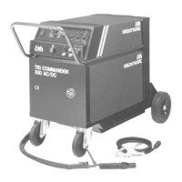
The parameters that can be adjusted are illustrated in
the figure below:
Pre-flow
Pre-flow is the period of time for which
gas flows after the torch switch is pressed
and before the HF arc is established, or until the torch
is lifted away from the workpiece in the LIFTIG
process. Variable 0-10 secs.
Start Amp
Immediately after the arc has been
established, the machine regulates the welding cur-
rent to the value stated in the Start Amp parameter.
Start Amp is set as a percentage of the required
welding current and is variable between 0-100% of
the welding current with a minimum value of 5 amps.
Slope-up
Once the arc has been established, the wel-
ding process enters a slope-up stage during
which the welding current is increased in linear
fashion from the value stated in the Start Amp para-
meter to the required welding current. The duration of
this slope-up time is variable 0-10 secs.
Slope-down
When welding has stopped by activating the
trigger, the machine enters a slope-down
stage. During this stage current is reduced from
welding current to Stop Amp over a period of time
called the slope-down time and variable 0-10 secs.
Stop Amp
The slope-down stage is completed when
the current level has fallen to the value
stated in the Stop Amp parameter. Stop Amp is stated
as a percentage of the required welding current and
is variable between 0-100% of the welding current
with a minimum value of 5 Amps.
Post flow
Post-flow is the period of time for which gas
flows after the arc is extinguished and is
variable 3-20 secs.
Reduced current
When four-times welding a reduced current
is activated by pressing the trigger briefly. This
reduced current is set to a percentage value of the
welding current and is variable between 0-100% of
the welding current.
H
Pulse welding
This panel controls the setting of the conditions for
pulse welding. The panel is divided into two sections:
the upper section being used for the selection of the
pulse welding function and the lower section for the
setting of parameters.
It is not possible to introduce or discontinue the use of
the pulse welding function during the actual welding
process.
Pulse:
Pulse welding function is operational.
No pulse:
Pulse welding function is not in operation and
it is not possible to set pulse-welding para-
meters.
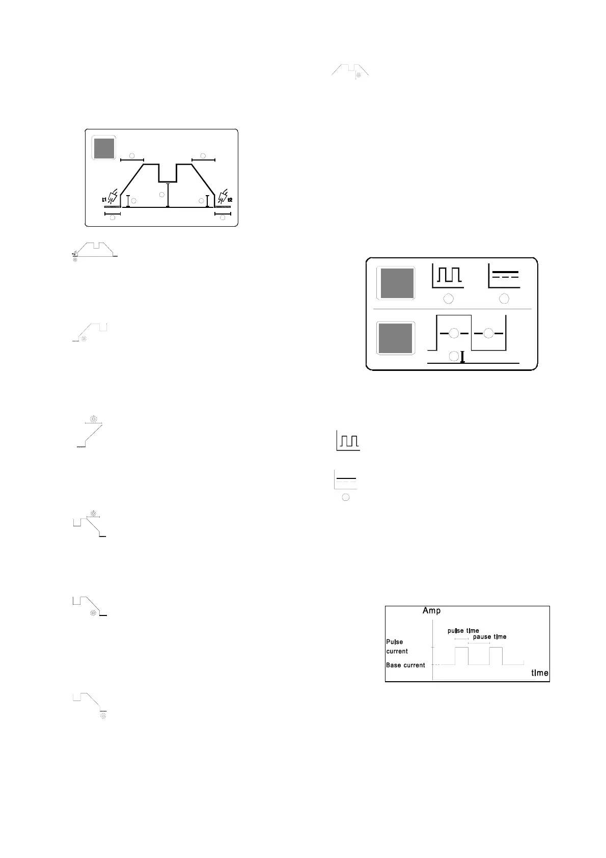
Pulse parameters
If the pulse welding function is in use then it is
possible to select and change the pulse parameters
during the welding process. The importance of the
pulse parameters can be seen from the illustration
below.