12
Connection and start-up
Cable dimensions
Welding current DC PULSE
200 A 35 mm² 35 mm²
300 A 50 mm² 70 mm²
400 A 95 mm² / 2x50 mm² 95 mm² / 2x50 mm²
500 A 2x70 mm² 2x70 mm²
Welding process Distance to
work piece
(a+b)
Total cable length
in welding circuit
(a+b+c)
MIG - IAC and pulse 10 m 20 m
MIG - non pulse 30 m 60 m
a
b
c
Connection of electrode holder for MMA
The electrode holder and earth cable are connected to
plus connection (10) and minus connection (8). Observe the
instructions from the electrode supplier when selecting polarity.
Adjustment of wire brake
The wire brake must ensure that the wire reel brakes sufficiently
before the welding wire runs over the edge of the reel.
The brake force is dependent on the weight of the wire reel and
wire feed speed. Factory setting is 15kg.
Adjustment:
• Dismount the control knob by
placing a thin screw driver behind
the knob and thereafter pull it
out.
• Adjust the wire brake by
fastening or loosening the self-
locking nut on the axle of the
wire hub.
• Remount the control knob.
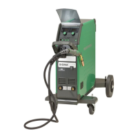
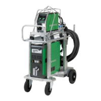
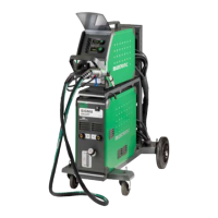
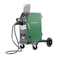
Lift instructions
The lifting points must be used (please see
figure) when lifting the machine.
The machine must not be lifted with
mounted gas bottle.
Do not lift the machine by the handle.
Do not step on the handle.
x4
Assembly of parts in wire feed unit
The pressure of the
thumbscrew is adjusted to
allow the wire feed roll
just to slide on the wire
when this is stopped at
the contact tip
 Loading...