19
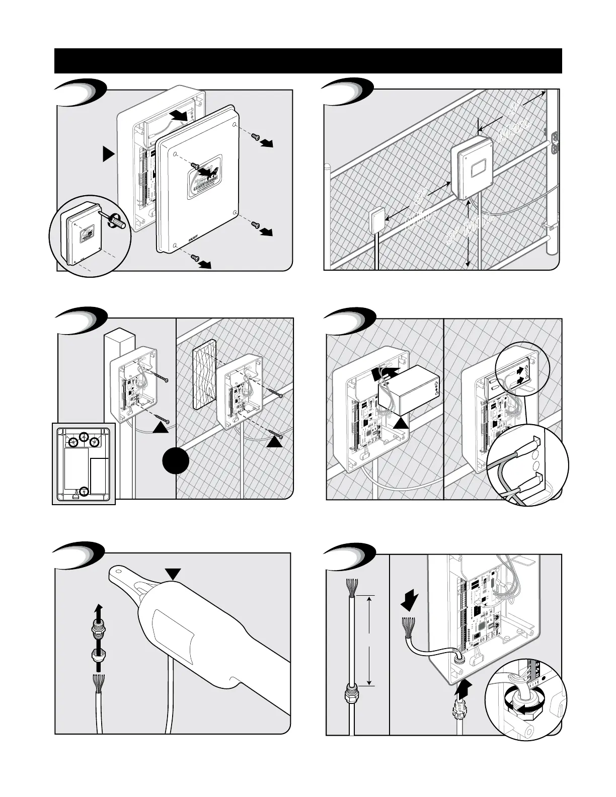
Control Box Installation
Remove control box cover.
15
A
1
Locate control box mounting area. IMPORTANT: Be sure to
mount box at least 3ft from AC power and 3ft off the ground.
3’
Min.
4’
Max.
2
3
W
W
OR
Mount control box to post or fence using screws. Position battery in control box as shown. Connect battery leads
from control board to battery. IMPORTANT: Red wire to (Red
Post) positive and black wire to (Black Post) negative.
15
RB500
12 Volt
/
7.0 Amp Mount
15
G
Black
Red
POS
NEG
4
1
15
FUSE
BAT T+
BAT T-
RECEIVER
GTO RCVR.
GTO
LOCK
AUX
RLY
POWER
INPUTS
CONTROL
INPUTS
MASTER CABLESLAVE CABLE
CONTROL INPUTS
2
RECEIVER
ALM
GTO RCVR.
GRN
BLK
RED
SHADOW
OPEN
EDGE
CLOSE
EDGE
3
6
6”
B
5
Feed cable 6” into box. Tighten strain relief nut to secure cable.Twist each end of the gate opener power cable’s 7 colored wires.
Feed cable through strain relief nut.
Control Box Installation