Operators Manual
21
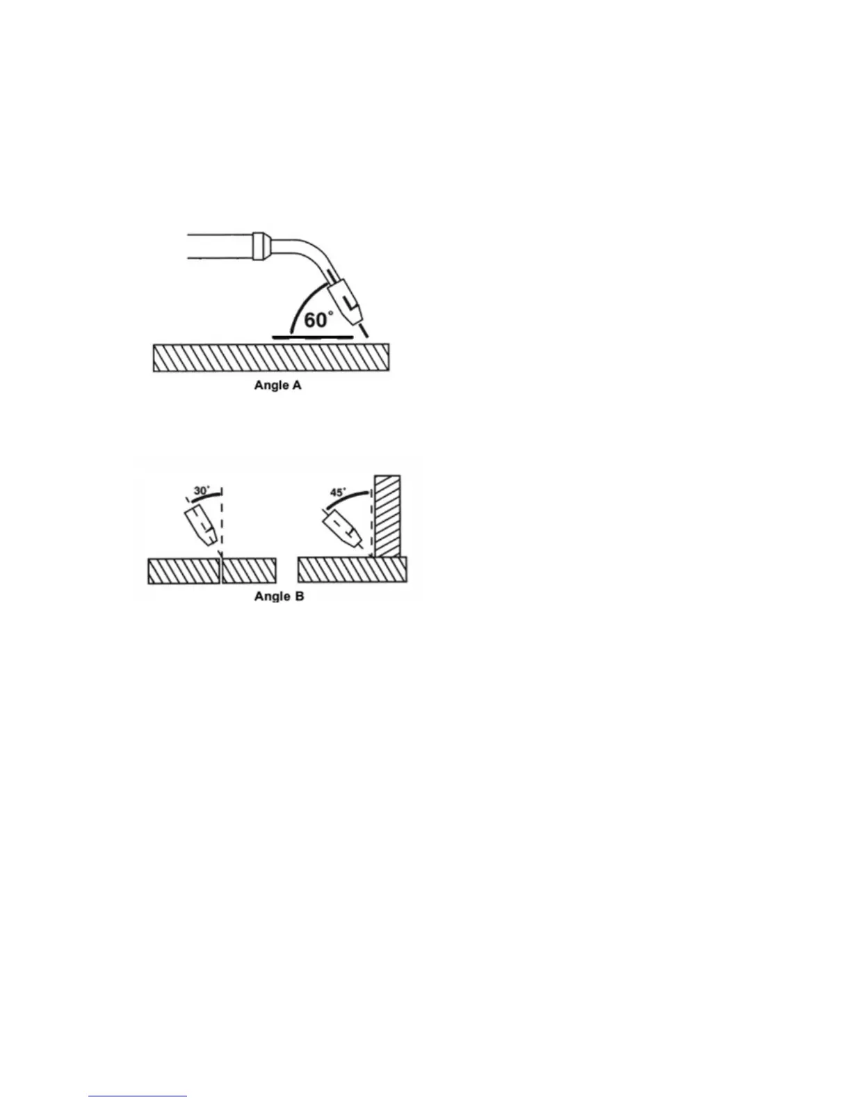
3. Posion the Torch to the Work Piece
There are two angles of the torch nozzle in relaon to the work piece that must be
considered when welding.
3.1. Angle A can be varied, but in most cases the opmum angle will be 60 degrees,
the point at which the torch handle is parallel to the work piece. If angle A is increased,
penetraon will increase. If angle A is decreased, penetraon will decrease also.
3.2. Angle B can be varied for two reasons: to improve the ability to see the arc in relaon
to the weld puddle and to direct the force of the arc.
4. Distance from the Work Piece
If the nozzle is held o the work piece, the distance between the nozzle and the work
piece should be kept constant and should not exceed 1/4 inch or the arc may begin
spuering, signaling a loss in welding performance.
5. Tuning in the Wire Speed
This is one of the most important parts of MIG welder operaon and must be done
before starng each welding job or whenever any of the following variables are changed:
heat seng, wire diameter, or wire type.
WARNING:
EXPOSURE TO A WELDING ARC IS EXTREMELY HARMFUL TO THE EYES AND SKIN!
Prolonged exposure to the welding arc can cause blindness and burns. Never strike an arc
or begin welding unl you are adequately protected. Wear ameproof welding gloves, a
heavy long sleeved shirt, trousers with no cus, high topped shoes, and an ANSI approved
welding helmet.
5.1. Connect the Ground Clamp to a scrap piece of the same type of material which you
will be welding. It should be equal to or greater than the thickness of the actual work
piece, and free of oil, paint, rust, etc.
5.2. Select a heat seng. Refer to set up chart in machine door.