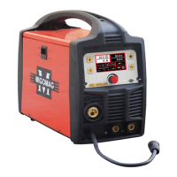
Migomag SIM 200 LCD
Model No ASIM200LCD
20
NOTE:
Slowly open the cylinder valve by turning it counterclockwise unl the cylinder pressure
gauge registers on the rst gauge of the regulator. Turn the adjustment knob clockwise
(right) slowly to increase gas ow to 15 lpm. To reduce the gas ow turn the adjustment
counterclockwise (le). The gas valve is located on the back panel of the welder and
acvated by the trigger. Gas ow should be heard when the trigger is acvated. No gas
ow will result in a harsh arc with excessive spaer, a smooth weld bead will be dicult to
obtain. Avoid unnecessary gas loss by closing the tank valve when nished welding.
6.3. Gas selecon
Dierent materials require dierent shielding gas when MIG welding, refer to the set up
chart inside the wire feed compartment.
Mild steel: Use gas mix consisng of Coregas 52 Argon 93%, CO2 5% and OXY 2%.
Stainless steel: Use a gas mix consisng of Coregas Sheildpro 20 Argon 98% and CO2 2%.
Aluminum or silicone bronze: Use 100% Argon.
Operaon
WARNING:
High voltage danger from power source! Consult a qualied electrician for proper
installaon of receptacle at the power source. This welder must be grounded while in use
to protect the operator from electrical shock. If you are not sure if your outlet is properly
grounded, have it checked by a qualied electrician. Do not cut o the grounding prong or
alter the plug in any way and do not use any adapters between the welder’s power cord
and the power source receptacle. Make sure the POWER switch is OFF before connecng
your welder’s power cord to a properly grounded 240VAC(220v-240v), 50/60Hz, single
phase, 15 amp power source.
The MIG Welding Operaon
1. Main Control Component
Power switch - The power switch supplies electrical current to the welder. When the
power switch is in the ON posion, the welding circuit is acvated. ALWAYS turn the power
switch to the OFF posion and unplug the welder before performing any maintenance.
AMP & VOLT Voltage selector - The voltage selector controls the welding heat. This
unit has innite voltage control. Refer to the label inside the welder side door for
recommended voltage selector sengs for your welding job.
Wire speed control - The wire speed control adjusts the speed at which the wire is fed out
of the welding torch. The wire speed needs to be closely matched (tuned-in) to the rate at
which it is being melted o. Some things that aect wire speed selecon are the type and
diameter of the wire being used, the heat seng selected, and the welding posion to be
used.
Note: The wire will feed faster without an arc. When an arc is being drawn, the wire speed
will slow down.
2. Hold the Torch
The best way to hold the welding torch is the way that feels most comfortable to you.
While praccing to use your new welder, experiment holding the torch in dierent
posions unl you nd the one that seems to work best for you.