OM-626 Page 10
3-1. Coolant System Rating
ssb1.1 10/91 – Ref. SB-130 607
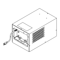
The cooling capacity curve shows
how much heat the unit can remove
from incoming coolant. Coolant ca-
pacity limited by torch/gun temper-
ature rating (see torch/gun owner’s
manual).
Figure 3-1. Heat Dissipation Curve
SECTION 4 – INSTALLATION AND OPERATION
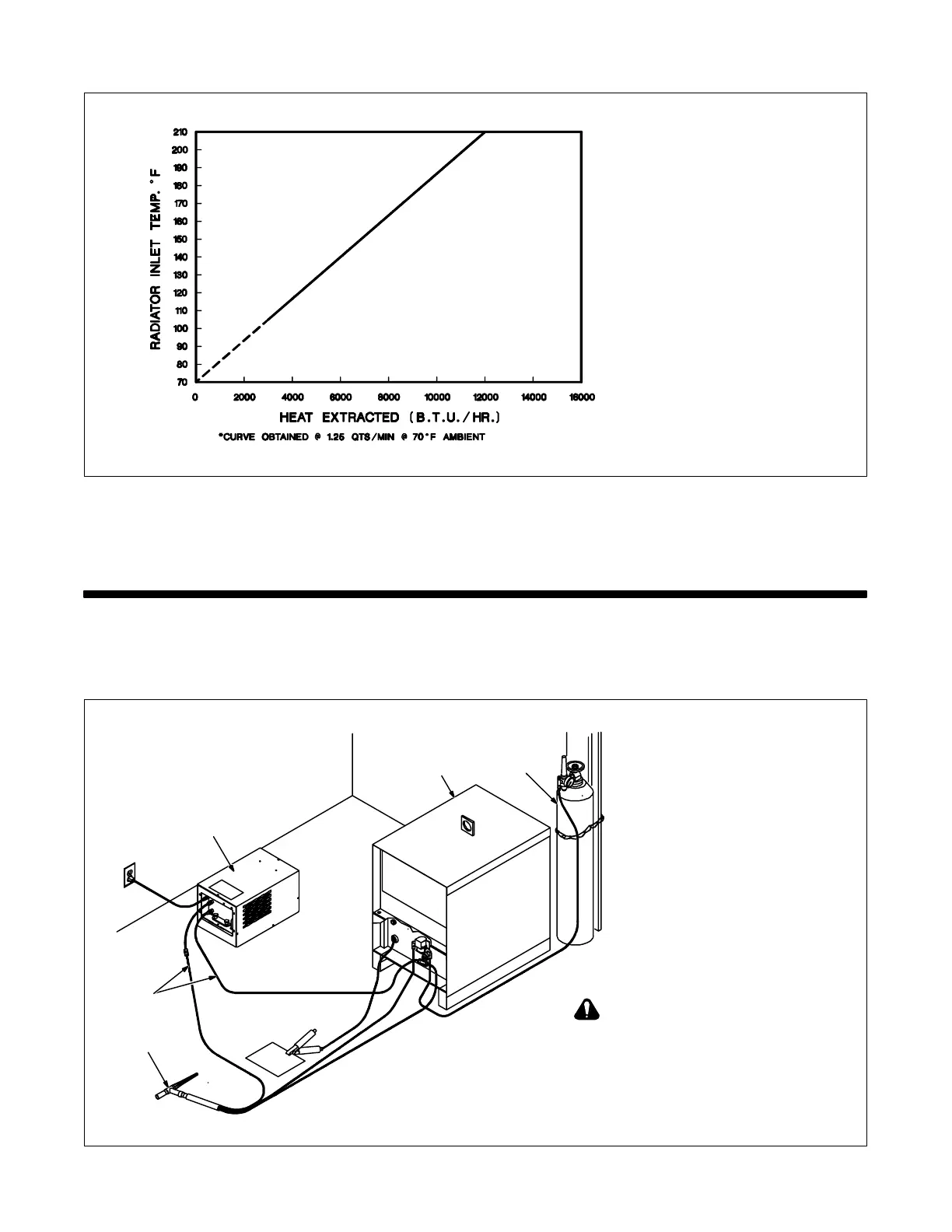
4-1. Typical Process Connections
A. Typical GTAW Connections
ST-159 300
1 Coolant System
2 Coolant Hoses
3 GTAW Torch
Obtain hoses with proper fittings
(see Section 4-4).
4 Gas Cylinder
5 Welding Power Source
1
3
5
4
2
Welding power source without water
valve shown. When using coolant
system with a welding power source
with a water valve, by-pass water
valve on welding power source by
connecting directly to torch/gun to
avoid overheating or damage to
coolant system.
Figure 4-1. Typical GTAW Connections