OM-626 Page 17
Table 5-1. Coolant System Trouble
Trouble Remedy Section
Coolant system does not work. Secure power cord plug in power receptacle. 3-5
Check line fuses or circuit breaker, and replace if necessary. – –
Thermal overload. Allow motor to cool. 5-5
Have Factory Authorized Service Station/Service Distributor
check Power switch and motor.
– –
No coolant flow. Add coolant. 4-3
Check for clogged hoses or coolant strainer. 5-2
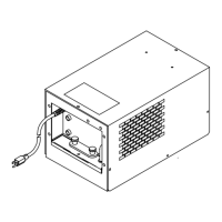
Disconnect pump, and check for sheared coupling. Replace
coupling if sheared (see Parts List for coupling location).
7
Decreased coolant flow rate. Add coolant. 4-3
Check for clogged hoses or coolant strainer. 5-2
SECTION 6 – ELECTRICAL DIAGRAMS
SA-135 796-A
Figure 6-1. Circuit Diagram For 115 Volts Model
SA-135 954-A
Figure 6-2. Circuit Diagram For 230 Volts Model