OM-626 Page 11
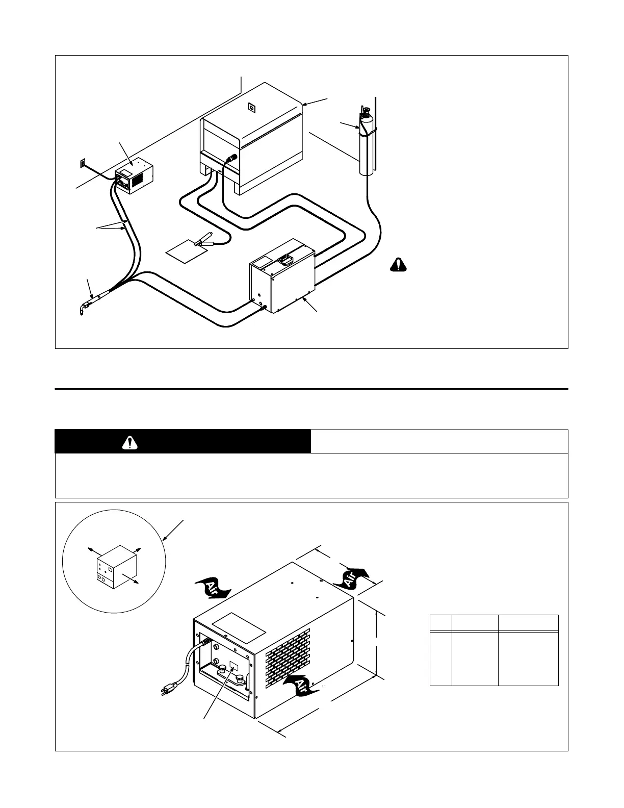
B. Typical GMAW Connections
ST-159 299
1 Coolant System
2 Coolant Hoses
Obtain hoses with proper fittings
(see Section 4-4).
3 GMAW Gun
4 Wire Feeder
5 Gas Cylinder
6 Welding Power Source
1
2
3
4
5
6
Welding power source without water
valve shown. When using coolant
system with a welding power source
with a water valve, by-pass water
valve on welding power source by
connecting directly to torch/gun to
avoid overheating or damage to
coolant system.
Figure 4-2. Typical GMAW Connections
4-2. Selecting A Location
WARNING
BLOCKED AIRFLOW causes overheating and possible damage to unit.
• Do not block or filter airflow.
Warranty is void if any type of filter is used.
ST-137 225-D
1 18 in (460 mm) Open Space
On Sides And Rear For Good
Airflow
2 Rating Label
Locate unit near correct input pow-
er supply.
Left
Right
Rear
Inches Millimeters
A 20-1/4 514
B 12-1/4 311
C 11-3/4 298
1
B
C
A
2
Figure 4-3. Location And Overall Dimensions