Complete Parts List is available at www.MillerWelds.com
OM-259 355 Page 50
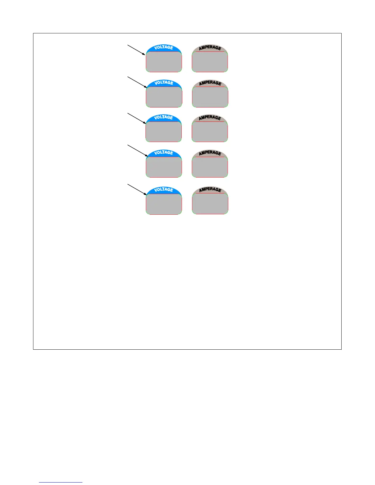
8-12. Voltmeter/Ammeter Help Displays
Use the Voltmeter/Ammeter help displays
to diagnose and correct fault conditions.
When a help code is displayed normal-
ly weld output has stopped but genera-
tor power output may be okay.
To reset help displays, stop unit and
then restart. See item 6 below to reset
Help 25 display.
1 Help 20 Display
Indicates a failure of meter display module
PC2, or the wiring between PC2 and main
control module PC1. If this display is
shown, have Factory Authorized Service
Agent check PC1, PC2, and the wiring be-
tween PC1 and PC2.
2 Help 21 Display
Indicates thermal protector TP1 on stabil-
izer Z1 has opened (Z1 overheated) or
thermistor TH1 on the main rectifier heat
sink has failed. If this display is shown,
have, allow unit to cool and reduce duty
cycle. If unit does not reset after cooling,
have Factory Authorized Service Agent
check TH1, and the wiring between TH1
and PC1.
3 Help 22 Display
Indicates the rectifier heat sink has over-
heated. If this display is shown, check gen-
erator cooling system and/or reduce duty
cycle. Keep engine access door closed
when running to maintain proper cooling
air flow past rectifier. Allow unit to cool be-
fore restarting. If problem continues, have
Factory Authorized Service Agent check
unit.
4 Help 23 Display
Can indicate a complete loss of generator
excitation, auxiliary power output, and
weld output or a failure of one of the rectifier
output SCRs. If generator output is lost,
see trouble “No generator power or weld
output.” in section 8-14B. If generator out-
put is okay, have Factory Authorized Ser-
vice Agent check the rectifier SCRs.
5 Help 25 Display
Indicates a remote device connected to
Remote Receptacle RC14 may be faulty.
Help 25 is also displayed whenever a re-
mote device has been connected to RC14
and then disconnected. Clear fault by stop-
ping and restarting the unit or by turning
Process/Contactor switch to another posi-
tion. If problem continues, have Factory
Authorized Service Agent check the re-
mote device, filter board PC6, and main
control module PC1.
2
1
HL.P
22
HL.P
23
HL.P
25
HL.P
20
HL.P
21
5
4
3
245 609
8-13. Maintaining Stainless Steel (Models With Optional Package)
Stainless steel is very resistant to rust and corrosion; however, it must be kept clean to ensure rust and corrosion resistance. Units used
in corrosive environments (chlorine or salt water environment for example) should be cleaned with mild soap and water frequently. If dirt
build−up occurs, use a stainless steel cleaner to remove build−up. With proper maintenance, stainless steel maintains its luster and appear-
ance.

 Loading...