B
Benjamin HammondAug 18, 2025
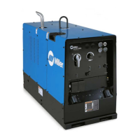
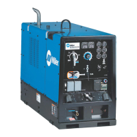
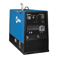
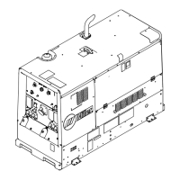
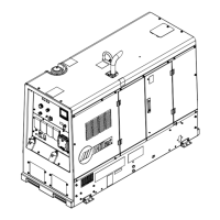
What to do if the Miller Big Blue 800 X Duo Air Pak Welding System displays 'IGBT TEMP'?
- EEdward WalkerAug 18, 2025
If your Miller Welding System displays 'IGBT TEMP', it indicates an IGBT module has overheated. First, inspect the generator cooling system and consider reducing the duty cycle. Ensure the engine access door remains closed during operation to maintain proper cooling airflow. Allow the unit to cool down completely before attempting to restart it. If the problem persists after these steps, it is recommended to have a Factory Authorized Service Agent inspect the unit.