D
David BradySep 23, 2025
What causes low open-circuit voltage on my Miller Big Blue 800?
- Ddouglas98Sep 23, 2025
Engine speed may need adjustment. Check position of Process/Contactor switch.
What causes low open-circuit voltage on my Miller Big Blue 800?
Engine speed may need adjustment. Check position of Process/Contactor switch.
What to do if my Miller Inverter engine cranks but does not start?
First, check the fuel level. The optional low fuel shutdown stops the engine if the fuel level is low. Reset supplementary protector CB13. Check the battery and replace if necessary.
What to do if my Miller Big Blue 800 engine starts but stops when the Engine Control switch is released?
Check the oil level. The automatic shutdown system stops the engine if oil pressure is too low or the engine temperature is too high.
Why does my Miller Big Blue 800 battery discharge between uses?
Turn the Engine Control switch S1 off when the unit is not running. Clean the top of the battery with baking soda and water solution, then rinse with clear water. Recharge or replace the battery if necessary. Periodically recharge the battery (approximately every 3 months).
What to do if my Miller Inverter engine does not run at idle speed?
Turn the Process/Contactor switch to any position but Remote-TIG. Allow circuit breaker CB14 to reset.
What to do if my Miller Big Blue 800 Inverter engine slowly stopped and cannot be restarted?
Check the fuel level. Check the engine air and fuel filters.
How to troubleshoot a Miller Big Blue 800 engine that is hard to start in cold weather?
Use the starting aid switch. Keep the battery in good condition and store it in a warm area off a cold surface. Use fuel formulated for cold weather (diesel fuel can gel in cold weather). Use the correct grade oil for cold weather.
Why does my Miller Inverter voltage/amperage control not work in Stick mode?
Place the Ampere Range switch in the lower range. The Voltage/Amperage control does not work with the Ampere Range switch in the highest range.
What causes high weld output on my Miller Big Blue 800 Inverter?
Check the position of the Ampere Range switch and the Voltage/Amperage Adjust control. The engine speed may need adjustment.
What to do if my Miller Big Blue 800 has no generator power output at AC receptacles, but weld output is okay?
Reset the receptacle supplementary protectors and the GFCI receptacle.
Explains warning symbols used in the manual to identify hazards.
Details hazards associated with arc welding processes and precautions.
Outlines potential dangers related to the engine and its components.
Details hazards associated with hydraulic systems and fluids.
Covers dangers related to compressed air equipment and its use.
Introduces symbols for installation, operation, and maintenance hazards.
Lists warnings related to chemicals known to cause cancer or birth defects.
Lists key safety standards and organizations for reference.
Discusses electromagnetic fields and their potential impact on medical implants.
Explains various symbols and their meanings used in the manual.
Details technical specifications for welding output, power, and engine.
Provides sound level measurements at different engine speeds and distances.
Lists physical dimensions, weight, and safe operating angles for the unit.
Shows voltage-amperage output capabilities for Stick and MIG welding modes.
Displays voltage-amperage output capabilities for DC TIG welding mode.
Illustrates typical fuel usage based on weld amperage and duty cycle.
Shows the generator's AC power output available at receptacles.
Indicates where to find the serial number and rating information for the product.
Provides instructions and safety precautions for installing the welding generator unit.
Details methods and precautions for securely mounting the welding generator.
Explains how to properly ground the generator frame for safety.
Instructions for installing the exhaust pipe, including safety direction.
Steps for installing an optional spark arrestor muffler for safety compliance.
Step-by-step guide for activating a dry charge battery, including safety precautions.
Provides instructions and safety notes for correctly connecting the battery.
Explains the function and operation of the optional battery disconnect switch.
Lists essential checks to perform on the engine before starting it.
Guides on correctly connecting weld cables to the output terminals for safety.
Table and guidelines for selecting appropriate weld cable sizes based on current and length.
Details connections and socket information for the Remote 14 receptacle.
Explains connections to the terminal strip T10 for routing leads.
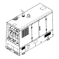
Identifies and illustrates the main controls on the welding generator's front panel.
Provides detailed descriptions and functions of each control on the generator.
Explains the function and settings of the process/contactor switch for selecting welding modes.
Guides on using remote controls for adjusting voltage and amperage in different welding modes.
Explains the display and function of the fuel/hour gauge and its indicators.
Describes the auxiliary power receptacles, circuit breakers, and their output ratings.
Outlines a schedule for routine maintenance tasks based on operating hours.
Explains the information found on the engine maintenance label for service intervals.
Instructions for using the optional oil pan heater to maintain engine oil temperature.
Details procedures for cleaning or replacing the air cleaner element.
Instructions for inspecting and cleaning the optional spark arrestor muffler.
Guides on checking the condition and length of generator brushes.
Notes that engine speed is electronically governed and requires service agent for adjustments.
Covers maintenance procedures for the engine's fuel and lubrication systems.
Explains the function of various protectors and circuit breakers for overload protection.
Provides tables listing common welding and generator power issues and their remedies.
Presents the overall electrical circuit diagram for the welding generator.
Explains wetstacking and its causes during engine run-in.
Details the procedure for running in the generator using a load bank.
Outlines the process for running in the generator using a resistance grid.
Guidance on selecting appropriate electrical equipment for use with the generator.
Instructions for grounding the generator frame to a vehicle for safety.
Explains how to properly ground the generator when supplying power to building systems.
Provides methods to calculate power requirements for various equipment.
Table showing power requirements for different industrial motors.
Table listing power requirements for common farm and home equipment.
Table detailing power needs for various contractor equipment.
Explains how to determine the starting power requirements for single-phase induction motors.
Guidance on generator output limits and starting loads.
Illustrates typical connections for supplying standby power with the generator.
Tables for selecting appropriate extension cords based on load and length.
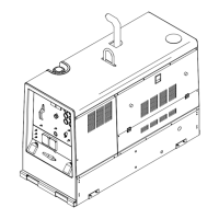
Exploded view and parts list for the main assembly of the generator.
Exploded view of the generator assembly with part numbers.
Exploded view and parts list for the control box assembly.
Exploded view and parts list for the front panel assembly.