OM-225 590 Page 67
Description
Part
No.
Dia.
Mkgs.
Item
No.
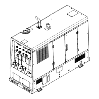
Figure 12−1. Main Assembly (Continued)
Quantity
57 087 341 BUMPER, door 1.000 OD x .750 high 4.. ............ .. ...............................
58 087 336 LATCH 2.. ............ .. ..........................................................
59 048 213 BAFFLE, air intake 1.. ............ .. ................................................
194 467 WASHER, flat (for baffle) 6.25 ID x 11.50 OD x .62 T buna 1.................. .. .............
60 023 313 CLAMP, hose 3.250-3.000 clp dia slftg 3.. ............ .. ...............................
61 225 643 TUBE, air intake 1.. ............ .. ..................................................
62 225 642 HOSE, air cleaner 1.. ............ .. ................................................
63 189 764 AIR CLEANER, intake 1.. ............ .. .............................................
64 165 785 HOSE, air cleaner 2.500 id 1.. ............ .. .........................................
*192 938 FILTER, air element primary 1................. .. ........................................
*♦192 939 FILTER, air element safety 1................ .. .........................................
65 203 460 BRACKET, mtg air cleaner 1.. ............ .. .........................................
66 237 006 ENGINE, Deutz dsl elec D914L03i (includes) 1.. ............ .. .........................
*249605 FILTER, oil 1.................. .... .....................................................
*249606 FILTER, fuel secondary 1.................. .... ..........................................
*066 271 V−BELT 1................. .... .......................................................
246989 KIT, Filter (Includes Fuel, Oil, And Air Filters) 1................... .. .........................
199 507 HOSE ASSY, oil drain 20.000 lg (includes) 1.................. .. ...........................
67 165 271 VALVE, oil drain 3/8−18 nptf 1.. ............ .... ......................................
68 176 529 FTG, hose brs barbed fem 1/2 tbg x 3/8 npt 1.. ............ .. ........................
69 113 854 HOSE, sae .500 id x .780 od xcoil 1.66ft.. ............ .... ..............................
023 562 CLAMP, hose .312 − .875 clp dia 1.................. .. ..................................
70 176 528 FTG, hose brs barbed elbow m 1/2 tbg x 1/2 npt 1.. ............ .. .....................
71 206 906 ADAPTER, oil drain fitting 1.. ............ .. ..........................................
72 047 235 WASHER, seal oil copper .879id x 1.059od 111−8737 1.. ............ .. ..................
73 195 745 SWITCH, pressure oil 1.5 bar nc cont 1.. ............ .. ...............................
74 195 746 SENDER, coolant temp & 130c switch 1.. ............ .. ...............................
75 083 476 MOUNT, eng/gen nprn .875 ID x 2.500 OD x 2.000 60 dur 2.. ............ .. ..............
76 Figure 12−4. GENERATOR 1.. ........ .. ....................................................
77 225 120 LABEL, warning moving parts can cause injury 2.. ............ .. .......................
78 176 236 BAFFLE, air outlet 1.. ............ .. ................................................
79 CLAMP, muffler (included with engine) 1.. ....................... ...............................
80 105 733 PIPE, muffler extension elbow 1.875 OD 1.. ............ .. .............................
81 165 739 BASE 1.. ............ .. ...........................................................
82 191 446 EXTRUSION, rubber w/adhesive 1.000 x 1.000 D (order by ft) 2.1ft.. ............ .. ........
83 173 352 EXTRUSION, rubber clamp/bulb (order by ft) 2.4ft.. ............ .. ........................
84 192 305 TRAY, base 1.. ............ .. ......................................................
85 176 167 NUT, 250-20 acorn nylon 6.. ............ .. ..........................................
86 192 303 ANGLE, mtg stabilizer 4.. ............ .. .............................................
87 Z1, Z2 192 296 STABILIZER 2.. . ... .. .....................................................
88 205 791 BRACKET, mtg fuse assembly (includes) 1.. ............ .. ............................
89 204 965 STRIP, insulation 6.. ............ .... ................................................
90 026947 STAND-OFF, insul .250-20 x 1.0 12.. ............. .... ..................................
91 F11-13, F21-23 027 267 FUSE, link 300 A 250 volt 6.. . .. ..........................................
92 192 304 PANEL, front lower 1.. ............ .. ................................................
93 233 953 LABEL, warning general precautionary CSA 1.. ............ .. ..........................
94 Figure 12−2. FRONT PANEL 1.. ........ .. ...................................................
95 175 256 INSULATOR, side RH 1.. ............ .. .............................................
96 192 300 SHROUD, generator LH 1.. ............ .. ...........................................
97 T2, T4 192 371 TRANSFORMER, 115V pri 24VCT 8A w/leads 2.. . ... .. ........................
98 192 301 SHROUD, generator RH 1.. ............ .. ...........................................
99 168 829 TRANSDUCER, current 1000A module max open loop 2.. ............ .. ................
100 192 299 SHROUD, generator center 1. ............ .. ........................................
101 194 021 CAPACITOR ASSEMBLY, (includes) 2. ............ .. ................................
162 817 BUS BAR, capacitor 2.................. .... .............................................
C15, C20 163 535 CAPACITOR, elctlt 6...... .. .... ..............................................
R4, R6 140 002 RESISTOR, WW fxd 10W 1....... ... .... ........................................
162 799 BRACKET, mtg capacitors 2.................. .... .......................................




 To Next Page