Do you have a question about the Miller DU-OP and is the answer not in the manual?
Lists supported welding types such as Stick, MIG, Flux Cored, and TIG.
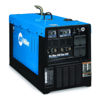
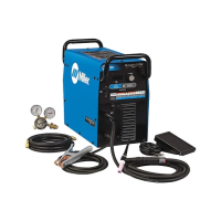
Brief overview of the welding generator's capabilities and features.
Introduces company values, product quality, and emphasizes the importance of safety.
Explains safety symbols (DANGER, WARNING, NOTICE) and hazard indicators.
Details specific risks during arc welding, including electric shock and contact hazards.
Critical information on preventing electrocution from live electrical parts.
Risks from welding byproducts like fumes and gases, and radiation from arc rays.
Hazards related to fire, explosion, noise exposure, and electromagnetic fields (EMF).
Dangers associated with the engine, including battery explosion, fuel fire, and exhaust sparks.
Risks from mechanical movement of parts and burns from hot engine or exhaust components.
Risks from hydraulic systems (fluid injection, moving parts) and compressed air equipment.
Hazards related to compressed air use and welding fire/explosion risks.
Risks from welding wire, static discharge to PC boards, and trailer instability.
Electromagnetic interference risks and California Proposition 65 chemical warnings.
References to applicable safety standards and EMF precautions.
Specific safety advice for users with medical implants near welding operations.
Glossary of symbols and terms used throughout the manual.
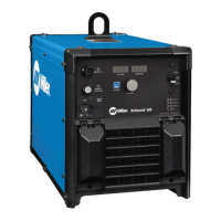
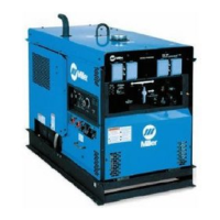
General overview of the welding generator's capabilities and dual operator modes.
Key technical performance data including weld output, power ratings, and engine details.
Physical characteristics and operating limitations for safe placement.
Information on fuel usage rates and AC generator power output capabilities.
Operational duty cycle limits and how the unit handles overheating.
Graphical representation of the generator's voltage and amperage output capabilities.
Identifying the unit's serial and rating information for reference.
Guidance on physical placement, movement, and airflow clearance.
Proper grounding procedures for mobile setups to prevent shock hazards.
Steps for installing and connecting the battery, including dry charge activation.
Installing the exhaust pipe and performing essential checks before starting the engine.
Safety considerations for connecting weld cables to output terminals.
Locating and understanding the function of various weld output terminals.
Wiring instructions for dual CC welding using separate work cables.
Wiring instructions for dual CC welding using a common work cable.
Wiring instructions for dual CV welding using separate work cables.
Wiring instructions for dual CV welding using a common work cable.
Wiring for dual CC/CV welding using separate cables.
Wiring for dual CC/CV welding using a common cable.
Wiring instructions for single CC welding operation.
Guide for choosing appropriate weld cable sizes based on current and length.
Procedure for installing the optional ether starting system.
Details on the remote control receptacle functions and pinouts.
Diagrams for connecting remote controls to the unit.
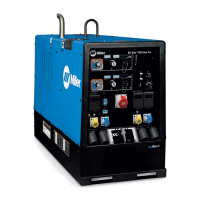
Description of the main engine controls, start/stop functions, and indicators.
Identification of the front panel weld controls like Process Selector and Amperage/Voltage.
Detailed explanation of each weld control's purpose and operation.
Information on using auxiliary power outlets, GFCI protection, and load limits.
Overview of regular maintenance tasks and recommended intervals.
Reference to the maintenance schedule sticker for engine and filters.
Procedure for cleaning or replacing the air filter element.
Procedures for servicing fuel filters, oil, and the fuel tank.
Adjusting engine RPM and maintaining the optional ether starting system.
Priming fuel lines and servicing the spark arrestor muffler.
Checking the condition and length of generator brushes.
Understanding and resetting circuit breakers and fuses for system protection.
Diagnosing and resolving problems related to welding output.
Diagnosing power output and engine operation problems.
Detailed schematic of the unit's electrical system for reference.
Explanation of wetstacking, its causes, and prevention methods.
Step-by-step guide for initial run-in using a load bank.
Step-by-step guide for initial run-in using a resistance grid.
Guidance on choosing appropriate electrical equipment and proper grounding methods.
Grounding for stationary installations and calculating equipment power needs.
Estimated power needs for various industrial motors.
Estimated power needs for farm and home equipment.
Estimated power needs for contractor equipment.
How to calculate the power required to start motors.
Guidance on how much power the generator can supply.
Typical connections for supplying standby power during outages.
Guidelines for choosing appropriate extension cords based on load and length.
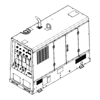
List of parts for the main assembly.
Parts for the main assembly and front control panel.
Parts for the side control panels (Welder B shown).
Additional parts for side control panels (Welder A and B).
Parts related to the generator assembly.
Additional parts for the generator assembly.
Parts for the rectifier assembly and various wiring harnesses.
Additional wiring harnesses for welder controls.
Additional wiring harnesses for welder controls.
Details of warranty periods and what is covered under Miller's True Blue warranty.
Conditions that void the warranty or are not covered, including consumables and misuse.
Area for owners to record equipment details like model name and purchase date.
How to get service, parts, and training from local distributors.
| Brand | Miller |
|---|---|
| Model | DU-OP |
| Category | Welding System |
| Language | English |