B
Brenda McfarlandAug 1, 2025
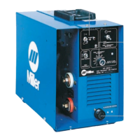
Why is it hard to establish an arc with my Miller HF-251D-1 Welding System?
- TTammy ShannonAug 1, 2025
If your Miller Welding System isn't creating a strong arc and you're struggling to start welds, try these steps: 1. Ensure the High Frequency Selector Switch is correctly positioned. 2. Keep the torch cable away from grounded metal. 3. Inspect cables and the torch for damage; repair or replace faulty parts. 4. Increase the High Frequency Intensity Control setting. 5. Use the correct tungsten size. 6. Check and adjust the spark gaps.