P
Philip AndrewsAug 2, 2025
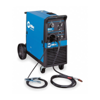
What to do if my Miller Millermatic 212 Welding System shows unit overload?
- FFrancisco ReyesAug 2, 2025
If your Miller Welding System experiences unit overload, allow the unit to cool down. Wait for the Over Temp light to turn off before attempting to weld again.