V
vincentdunnJul 31, 2025
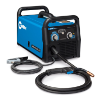
How to fix Miller Millermatic 250X Welding System when there is no wire feed?
- PPeter YangJul 31, 2025
To fix the issue, you can try the following: Reset circuit breaker CB1, turn the Wire Speed control to a higher setting, clear any obstruction in the gun contact tip or liner, readjust drive roll pressure, change to the correct size drive rolls, rethread the welding wire, and check the gun trigger and leads, repairing or replacing the gun if necessary. If the voltmeter display shows 'H – –' message, it indicates that thermostat TP1 is open and the unit is overheated. If problems persist, consult a Factory Authorized Service Agent to check the main control board.