Do you have a question about the Miller ProHeat 35 and is the answer not in the manual?
Explains hazard symbols used in the manual for safety.
Details hazards associated with induction heating operations and necessary precautions.
Details additional symbols for installation, operation, maintenance, and specific hazards.
Information on chemicals known to cause birth defects or cancer.
Lists key safety standards and where to obtain them.
Explains electromagnetic fields and their potential interference with medical implants.
Provides essential instructions for safe operation, maintenance, and handling.
Explains additional safety symbols, some specific to CE products.
Provides definitions for various symbols used in the manual, including electrical and operational terms.
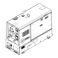
Details the location of serial number and rating labels on the machine.
Lists output frequency, rated output, required inductive reactance, and input amperage.
Details IP Rating and Electromagnetic Compatibility (EMC) requirements.
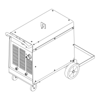
Provides guidelines for choosing a suitable location for the unit, considering airflow and safety.
Lists the physical dimensions and weight of the equipment.
Details electrical service requirements, including voltage, amperage, and conductor sizing.
Step-by-step instructions for connecting 460/575 volt 3-phase input power.
Instructions for connecting 400/460 volt 3-phase input power for IEC and CE models.
Details how to make coolant jumper connections for system configuration.
Guides on connecting output cables for single, dual, air-cooled, and liquid-cooled configurations.
Information and pinout for the Remote 14 Receptacle (RC14) for remote control.
Details the RC9 receptacle and socket information for temperature recording.
Explains the secondary insulation protection feature and its operation.
Describes the 115V AC receptacle and how to locate thermocouples for accurate heating.
Details methods for attaching welded and contact thermocouple sensors for temperature measurement.
Guidance on locating and using non-contact temperature sensors for optimal control.
Identifies and describes the function of each control button and indicator on the front panel.
Lists essential safety equipment required for operating the unit.
Explains how the system configures itself based on connected heating devices.
Provides guidelines for using multiple systems and initial system setup procedures.
Details how to reset to factory defaults and program heating processes.
Explains programming four temperature-based processes: Preheat, Bake-Out, PWHT, Custom Program.
Details programming for Bake-Out process, including temperature, soak time, and cool rate.
Describes programming for PWHT, including ramp and soak parameters.
Explains PWHT operation and how to create custom heating programs.
Details operation modes: Remote Control, Power vs Time Control, and Manual Control.
Explains Manual Control and Rolling Inductor modes, including travel detection.
Describes Run Status screens for monitoring Preheat, Bake-Out, PWHT, and Custom Programs.
Details Run Status screens for Manual, Remote, and Power vs Time control modes.
Explains system parameters and how to operate the cooler unit.
Describes the system check routine upon power-up and real-time operation.
Details power source output characteristics based on configuration and coil type.
Describes Rolling Inductor output amperage vs. heating time and travel speed.
Daily visual inspections of cords, cables, and labels.
Maintenance checks performed every 3 months, 6 months, and annually.
Lists the equipment required for calibration verification.
Step-by-step guide for performing calibration verification and TC input/output checks.
Steps to complete after calibration verification, including label placement.
Explains symbols used to indicate safety instructions during servicing.
Details hazards like electric shock, fire, flying metal, and induction heating burns during servicing.
Covers falling equipment, overuse, HF radiation, EMF, and general servicing instructions.
Explains the Fault LED, Limit LED, and LCD display for diagnostics.
Describes limit conditions, how they are indicated, and options for resolution.
Lists limit condition codes and provides additional information for troubleshooting.
Explains fault conditions, their indications, and system response.
Lists fault condition codes and provides additional information or required service.
Troubleshooting guide for infrared sensors and description of system diagnostic screens.
Explains parameters shown in system diagnostic screens, including voltage, temperature, and coolant status.
Lists firmware versions, PC board names, and compatibility information.
Procedure for safely measuring input capacitor voltage after power disconnection.
Instructions for safely blowing out dust and debris from inside the unit.
Lists parts for the front and side panels, doors, hinges, and fans.
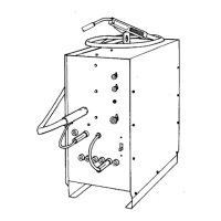
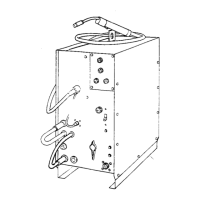
Lists components of the front and rear panels, including receptacles and circuit cards.
Parts list for the right windtunnel assembly for 460-575V models.
Parts list for the right windtunnel assembly for 400-460V models.
Parts list for the left windtunnel assembly.
Lists parts for air-cooled output extension cables.
Parts for liquid-cooled output extension cables.
Lists components for heating cables.
Parts list for the quick connect to quick connect hose assembly.
Lists various sizes and types of induction blanket and sleeve components.
Lists all components for the complete rolling inductor assembly.
Parts for the rolling inductor mounting arm assembly.
Lists components for the rolling inductor stand assembly.
Lists components for the travel sensor assembly with mounting bracket.
Parts list for the IR assembly with mounting bracket.
Parts for the IR TC control box assembly.
Lists parts for the regulator-filter air/oil separator assembly.
| Power Source | Electric |
|---|---|
| Weight | 27 lb (12.3 kg) |
| Dimensions | 18 in x 12 in x 12 in (457 mm x 305 mm x 305 mm) |
| Input Frequency | 50/60 Hz |
| Output Power | 35 kW |
| Fuel Type | Electric |