M
Michael WaltonSep 9, 2025
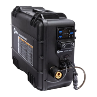
Why is the Miller SuitCase X-TREME 12VS arc voltage on meter board PC20 not accurate?
- MMatthew MontgomerySep 9, 2025
The arc voltage on the meter board PC20 of your Miller Welding System shows weld voltage at the feeder. Due to voltage drops in the weld cables, arc voltage at the feeder will not match arc voltage at the welding power source. Also, if weld time is less than 8 seconds the displayed arc voltage at the feeder may not be accurate because of voltage averaging. Check the Motor Control (PC1) and connections, and replace if necessary.