Chapter 1. Controls
PELLERIN MILNOR CORPORATION
Chapter 1
Controls
BICWCO02 (Published) Book specs- Dates: 20070507 / 20070507 / 20070507 Lang: ENG01 Applic: 42032F7W 42044WP2
42044WP3 48040F7W 60044WP2 60044WP3
1.1. Controls on Mark VI Non-Tilting Washer-extractors
Refer to other parts of this document (Section 1.1.2 through Section 1.1.5) for the location and
basic function of individual controls. Don't use this document as instructions for operating the
machine.
1.1.1. Where are the Controls?
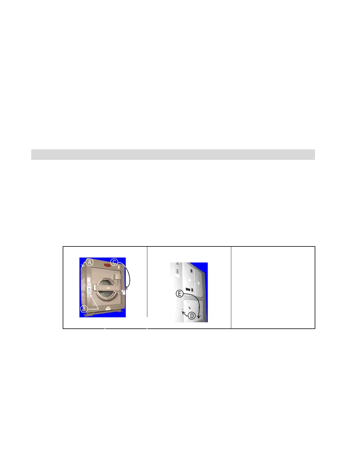
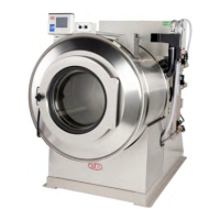
The essential controls for normal operation are located on the front control panel (Figure 1)
(Figure 3). Additional controls and connections are located elsewhere on the machine, as
described here.
Figure 1: Locations of Controls
Front Left View Rear View Legend
.
A. Microprocessor control
box (68036F_B shown)
B. Control panel
C. Manual supply flush
button
D. Hydraulic pressure gauge
for loading door
E. Air pressure gauge for tilt
system (behind lower rear
panel)
1.1.2. Where do I Connect the Data Storage Device?
The microprocessor box in the upper rear corner of the machine left side panel (see Figure 1)
contains a DIN-type connection for serial communications. Use this connection, labelled as
shown in Figure 2, with a serial data transfer device to save or restore machine programming and
configuration memory.
7