18
Instruction Manual
6.6 EXPLOSION PROOF PRESSURE
SWITCH
ALWAYS WIRE IN ACCORDANCE
WITH LOCAL OR NATIONAL
CODES. BE SURE ALL LIVE SUPPLY CIRCUITS ARE
DISCONNECTED BEFORE WIRING TO THE SWITCH. MAXIMUM
RECOMMENDED WIRE SIZE IS #14 AWG.
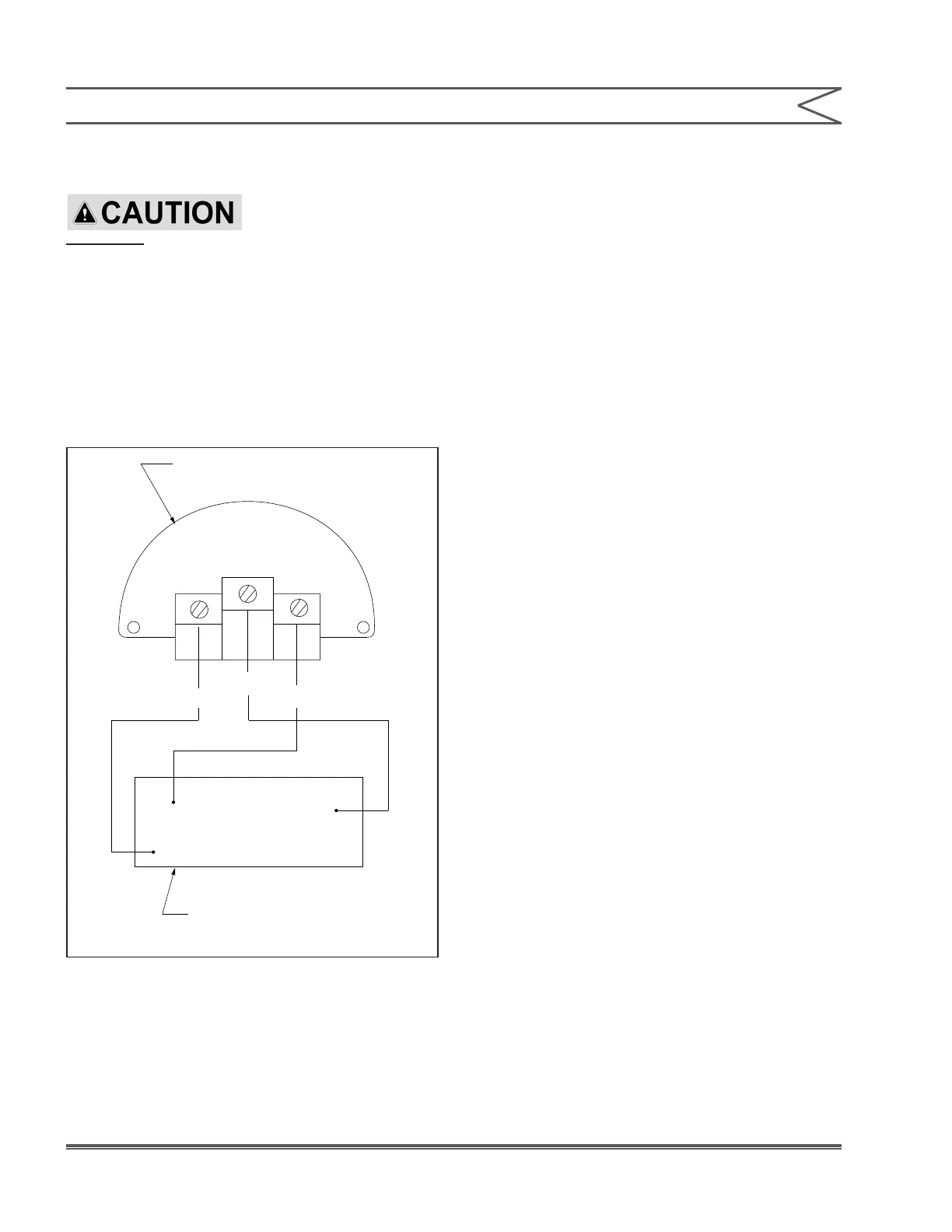
The three switch terminals are clearly labeled
“Com” (common), “NO” (normally open), and
“NC” (normally closed). A grounding screw is
also provided. Keep wires as short as possible
to prevent interference with the plunger and
differential switch wheel inside the switch.
IMPORTANT
Connections must always be made through cable
connectors which maintain the integrity of the
NEMA 4 switch or Explosion Proof enclosure.
6.7 START-UP
1. Refer to the manual for pump installation and
start-up instructions.
2. During the initial installation, following any
disassembly of the leak detection system, or if
the pump has not been operated for a prolonged
period, a short break-in procedure for the leak
detector system is required. On duplex pumps,
be sure to follow directions on both sides of the
pump.
a. Open the bleed valve(s) on the leak detection
system.
b. Operate the pump at 100% capacity and
normal system operating pressure. Air and a
small amount of oil may leak from the bleed
valve(s).
c. After a minimum of ten minutes of operation,
close the bleed valve(s).
The break-in operation purges any air and excess
oil which may be trapped in the intermediate ring(s).
The leak detection system is now operational.
Customer Connections
NO
COM
NC
(Violet)
(Blue)
(Black)
NO
COM
NC
Internal SPDT Switch Rated
15A, 120/240/480 VAC
Figure 1. Pressure Switch Wiring Diagram
SECTION 6 - INSTALLATION & OPERATION (PRESSURE SENSING SYSTEM)