5
180
AB
5.
AB
1'
B
B
6. Adjust the height of the tool (using the tripod or
by adding shims, if required) to align the laser
cross directly onto point II on wall B. Allow the
tool to self-level.
7. Rotate the tool 180° without changing the height,
allow it to self-level, and mark the centre of the
laser cross on wall A (point III). Point III should
be aligned as vertically above or below point I on
wall A as possible.
180
A
d
8.
mode and Horizontal Points mode.
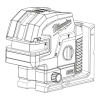
1. Turn the tool to
ON and to Horizontal Level Line
Horizontal Leveling Accuracy
It is also suggested to mount the Laser Level to a
Tripod for easy adjustment.
A
B
10 m
5 m
2. Mark the centre of the plumb point on the wall
(point I). Also, mark the centre of the plumb point
on the opposite wall (point II).
3. Rotate the tool 180°. Align the centre point of the
laser beam directly onto the wall point II.
4. Mark the centre point of the laser beam on wall
A (point III).
5. The distance d between marked points I and III on
wall A indicates the actual deviation (d) of the tool.
A
B
d
10 m
5 m
6.
Move the tool within 30 cm of wall B. Allow the
laser to self level. Align the laser cross in the
general direction of point II on wall B.
The distance between points I and III on wall A is
the height deviation (d) of the tool. This distance
should not exceed 3.18 mm (max.) at 10 m
(12.7 mm at 40 m). For the Measuring distance
of 2 x 20 m = 40 m, the maximum allowable
deviation (d) is: 40 m x ±3.18 mm ÷ 10 m =
±12.72 mm
For the Measuring distance of 2 x 10 m = 20 m,
the maximum allowable deviation (d) is:
20 m x ±3.18 mm ÷ 10 m = ±6.36 mm Thus, the
difference d between points I and III should not
exceed 6.36 mm (max.) at 20 m.
Securely mount the tool on one side of the room
and centred between walls A and B. Direct the laser
lines toward the other side of the room such that the
horizontal line appears on both walls A and B. Allow
the laser to Self-Level.
A free measuring space of approximately
10 m x 10 m on a firm surface between two walls or
structures A and B is required for the check.