9-86 Structure and Assembly/Disassembly
Non-moving assembly type
a) See Chapter 9.3.6, 9.3.8 and 9.3.9 for details.
b) Unscrew 3 M4 X 12 cross panhead screws on UC-0.5 with the screwdriver (M3, M4) to pull the
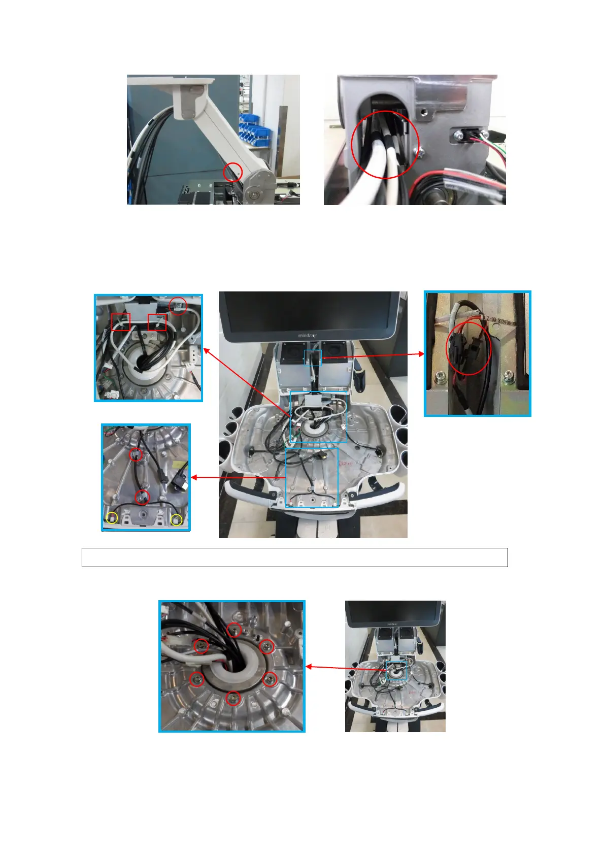
cables out, and cut two tie cables CHS-4X150 off Open the clip from the left/right speaker
assembly. Drag the power supply cable to the base of the keyboard.
Tie the cables according to the figure shown below when installing.
c) Unscrew 6 M5 X 16 round inner head screw from the keyboard base by M5 spanner to remove
the keyboard base upwards.
d) Unscrew 3 M4 X 12 cross panhead screws from the lower support arm cover with the
screwdriver (M3, M4) to remove the lower support arm cover.
Power supply cable of
left/right speaker
assembly
 Loading...


