Test Solutions - User Guide Page 6
RCM Series Compact Modular Test Systems 4-Oct-17 (A3)
3. PHYSICAL DESCRIPTION
3.1. RCM-100 Series
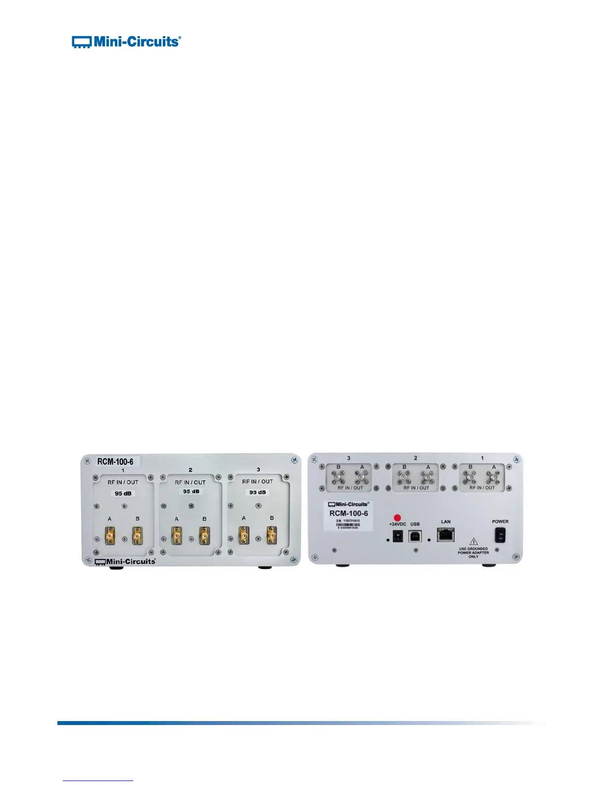
Mini-Circuits’ RCM-100 Series multi-channel attenuator systems are housed in a compact
aluminum case measuring 8.25” wide x 4.25” high x 8.25” deep (210 x 108 x 210 mm). The front
panel is fabricated with three windows, each measuring 2.43” wide x 3.35” high (62 x 85mm),
which can be specified with the required RF programmable attenuator components. 3
corresponding windows on the rear panel house the second connector for each programmable
attenuator channel. All RF connections are SMA female.
The rear panel of the unit includes inputs for a standard 24V DC power supply (AC mains
adapter included), USB and Ethernet connections for software control and a hardware power
switch. The identification sticker at the left edge contains the model name, serial number, and
control board number.
The modular chassis structure allows a variety of custom attenuator configurations to be built
and shipped to customers within 2 weeks or less. Each hardware window may be configured
with the user's choice of 1 or 2 programmable attenuators from the following models:
• 0 to 30 dB range, 0.25 dB step size, 1 to 6000 MHz
• 0 to 60 dB range, 0.25 dB step size, 1 to 6000 MHz
• 0 to 90 dB range, 0.25 dB step size, 1 to 6000 MHz
• 0 to 110 dB range, 0.25 dB step size, 1 to 6000 MHz
• 0 to 120 dB range, 0.25 dB step size, 1 to 4000 MHz
• Additional models up to 8 GHz are also available on request
Figure 1: Front & rear panel of RCM-100-6 multi-channel programmable attenuator