Test Solutions - User Guide Page 25
RCM Series Compact Modular Test Systems 4-Oct-17 (A3)
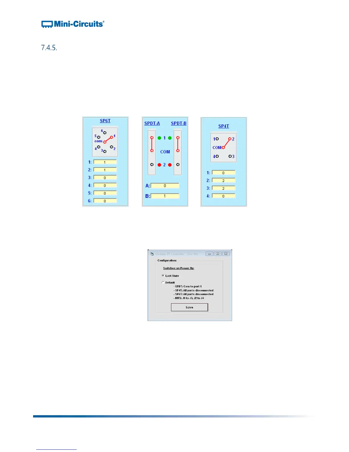
Switch Control Features
Switch Displays:
o The switch displays show a visual representation of each switch with the active
path highlighted red
o The switch state is changed by clicking the port that the common port should be
connected to
o The yellow cells at the bottom of the display indicate the switch counts, with a
separate count for each port of the switch (ie: the number of times that the
common port has been connected to it)
Figure 21: Switch control displays for SP4T switch, pair of SPDT switches and SP6T switch
Switch Power-Up Settings:
o The switch power-up settings are accessed by clicking the "Set Switches on
Power Up button"
Figure 22: Switch power-up options
o The options for power up are:
Last State: The system powers-up with the switches in the same state as
they were when last powered off
Note: It is important that the GUI is safely closed before powering off the
system in order for this feature to operate correctly
Default:
SPDT: Com to port 1
SP4T / SP6T: All ports disconnected
Transfer switch: J1 to J3, J2 to J4