miniDSP Ltd, Hong Kong / www.minidsp.com / Features and specifications subject to change without prior notice 9
2.2.2 I2S Clock lines
There are three clock lines. These clocks are always outputs. The connected circuitry must therefore be set to run in
slave mode and accept its clocks from the USBStreamer. (The USBStreamer always runs as clock master; it cannot be
set to run as a slave.)
MCLK The master clock for both playback and recording. This pin is an output only.
LRCLK The frame synchronization clock, also known as the word clock. This clock is equal to the sampling
frequency (Fs) of the audio signal. This pin is an output only.
BCLK The bit clock (also known as shift clock or system clock). This is always equal to 64 x Fs. This pin is an
output only.
The following table summarizes the relation between the clocks. Be sure to double-check that connected circuitry
will accept the clocks at the frequencies and ratios listed here:
2.2.3 TDM Clock lines
The clock lines are the same as per I2S above. Just a different clock rate.
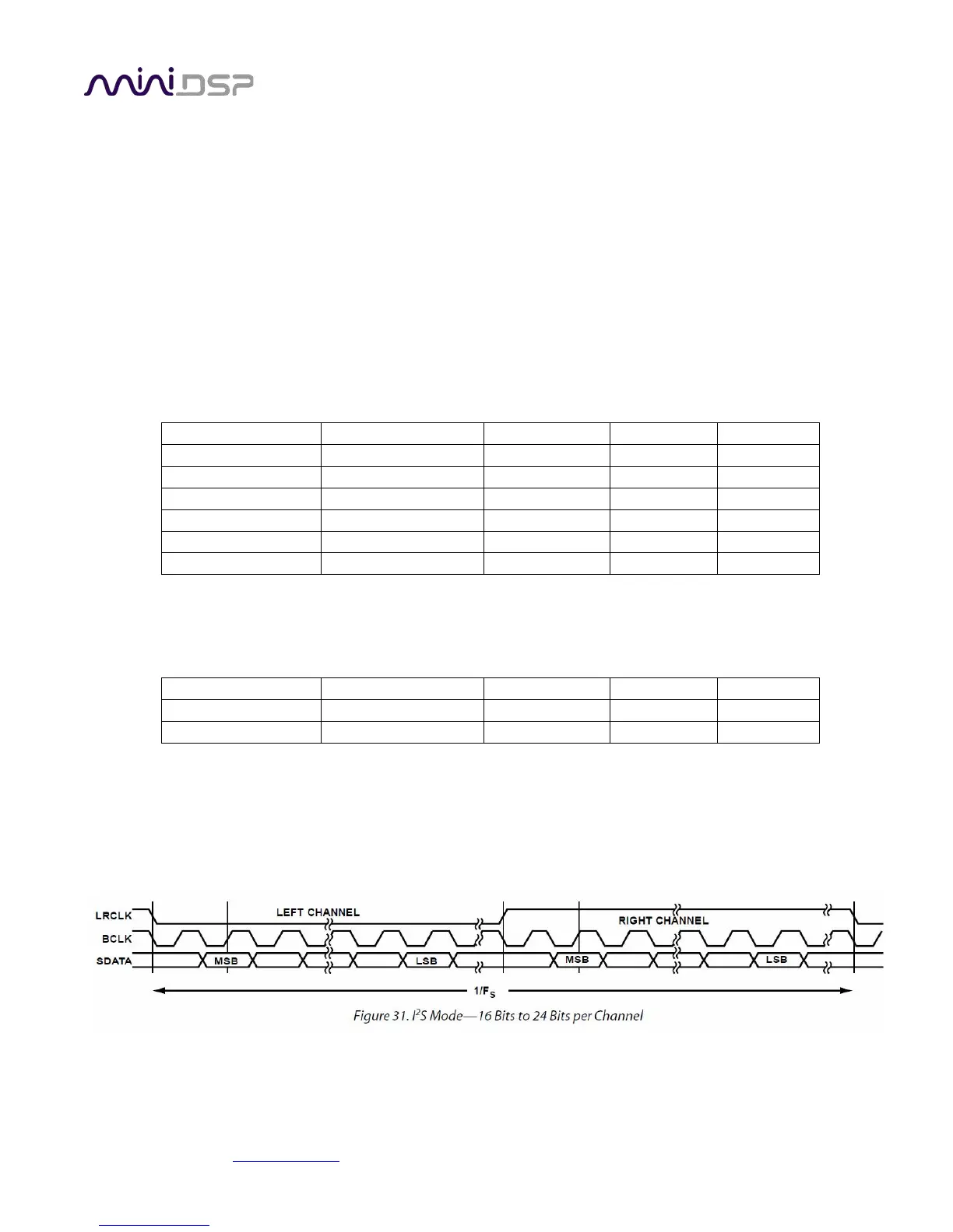
2.2.4 I2S Data lines
There are four lines for input data, and four line for output data (as indicated in the pinout on the previous page).
Each line carries two audio channels, in either 16-bit or 24-bit format. The expected I2S data format and timing is
shown in this diagram: