EasyManuals Logo

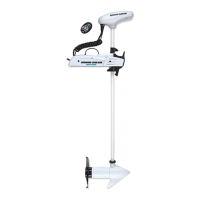
MINN KOTA RIPTIDE POWERDRIVE Installation Guide

MINN KOTA RIPTIDE POWERDRIVE
13 pages
To Next Page IconTo Next Page
To Previous Page IconTo Previous Page
Page #7 background imageLoading...
Page #7 background image
6
i. It is recommended to mark at least 6 of the 12 holes in the Base Extrusion and to have a minimum of two bolts on each side that are located the farthest apart. Ideal
installation would allow for 6 bolts to be used, with a minimum of 4.
j. Drill through the deck of the boat using a 9/32″ Drill Bit on the marked locations.
7
ITEM(S) NEEDED
#4 x 6 /#1 x 6
k. Put a 1/4-20 x 3-1/2″ (Item #1) screw in each of the drilled locations. The screw should pass through the Base Extrusion and the boat deck. If the rubber washers (Item
#4) are used, they should sit between the Base Extrusion and boat deck. Make sure to secure the motor with screws on each side of the Base Extrusion.
8
ITEM(S) NEEDED
#2 x 6/ #3 x 6
l. Place a Flat Washer (Item #2) and then a Nylock Nut (Item #3) at the end of each screw as shown and secure. Make sure all hardware is secure.

Other manuals for MINN KOTA RIPTIDE POWERDRIVE

Questions and Answers:

Question and Answer IconNeed help?

Do you have a question about the MINN KOTA RIPTIDE POWERDRIVE and is the answer not in the manual?

MINN KOTA RIPTIDE POWERDRIVE Specifications

General IconGeneral
Water TypeSaltwater
Speed ControlVariable
Digital MaximizerYes
i-Pilot LinkOptional
Speed SettingsVariable
WeightVaries by model
Voltage12V, 24V
Shaft Length48", 54", 60"
Control TypeFoot Pedal, i-Pilot, or i-Pilot Link
SteeringElectric Steering
Mounting LocationBow
Battery Requirement12V or 24V Deep Cycle Marine Battery
Motor TypeElectric
Warranty2 years
Thrust55 lbs
i-PilotAvailable on select models

Related product manuals