7
6
English
INSTALLATION PLACEMENT
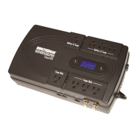
Output Power Receptacles
NEMA 5-15P W/10 ft cord
Model # Input Power Plug
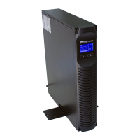
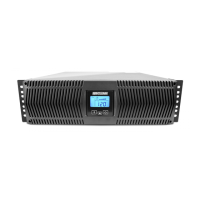
PRO1000RT
PRO1500RT
6-NEMA 5-15R Battery Backup & Surge
2-NEMA 5-15R Surge Only
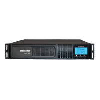
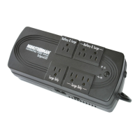
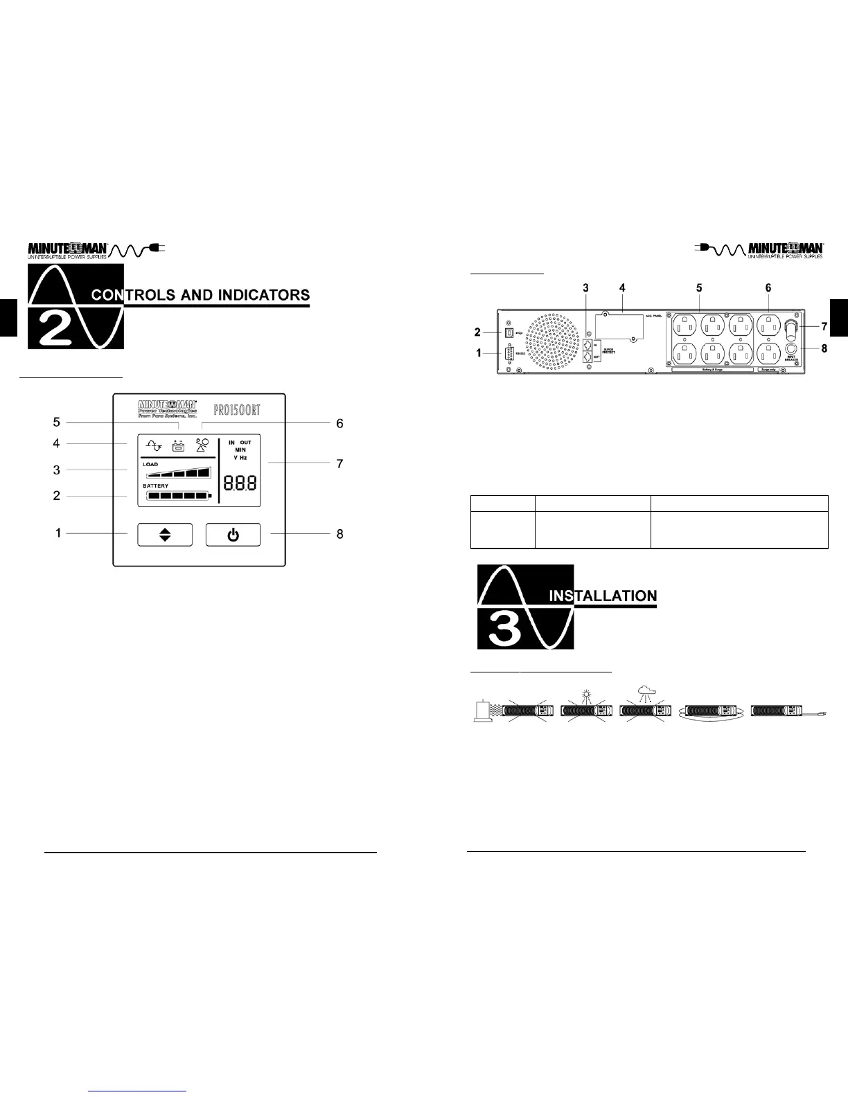
REAR PANEL
1. RS232 Comminucations Port is for UPS monitoring and control.
2. USB Communications Port is for UPS monitoring and control.
3. The RJ11/45 are used for phone/fax/modem and network protection.
4. Accessory Slot is for option cards.
5. Battery Backup & Surge output receptacles for mission critical equipment.
6. Surge ONLY output receptacles for non-critical equipment.
7. Input power cord is for connecting to the Utility Power.
8. Input circuit breaker is for protection against an excessive overload.
English
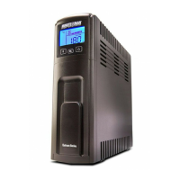
CONTROL PANEL
1. Scroll Button: To scroll through the UPS parameters.
2. Battery Capacity Bar Graph: Displays the amount of Battery Capacity
available in the AC and Battery mode.
3. Load Capacity Bar Graph: Displays the amount of load connected to the
UPS in the AC and Battery mode.
4. AC normal and Boost/Buck mode Icon: Illuminates when the UPS is in the
AC normal mode and flashs when the UPS is in the Boost or the Buck
mode.
5. On-Battery Icon: Illuminates when the UPS is operating in the Battery mode.
6. Overload Icon: Illuminates when the amount of load attached to the UPS
exceeds its power rating,
7. UPS Parameters and Error codes:
Input - Voltage and Frequency.
Output - Voltage and Frequency.
Estimated Runtime (minutes) - AC normal and Battery mode.
S.L.F - A site wiring fault has been detected.
FAL - An internal fault has been detected.
8. On/Off/Test Button: To turn the UPS On/Off and to perform a ten-second
battery test.
This UPS series is only intended to be install in an indoor temperature con-
trolled environment that is free of conductive contaminants. DO NOT operate
the UPS in: extremely dusty and/or unclean areas, locations near heating de-
vices, water or excessive humidity, or where the UPS is exposed to direct
sunlight. Select a location, which will provide good air circulation for the UPS at
all times.
Route power cords so they cannot be walked on or damaged.
Typi-
cal battery life is 3 to 5 years. Environmental factors do affect battery life. High
temperatures, poor utility power, and frequent, short duration discharges have a
negative impact on battery life.