1212
1212
12
1. Plumbing1. Plumbing
1. Plumbing1. Plumbing
1. Plumbing
Read the section
"Important Safety Information""Important Safety Information"
"Important Safety Information""Important Safety Information"
"Important Safety Information" first.
1.1.1.1.
1.1.1.1.
1.1. A maintained pressure of at least
1 bar1 bar
1 bar1 bar
1 bar is recommended for the product up to a
maximum static pressure of
10 bar10 bar
10 bar10 bar
10 bar.
Thermostatic performance will be maintained down to
0.5 bar0.5 bar
0.5 bar0.5 bar
0.5 bar maintained
pressure. However, this will result in reduced power and therefore reduced flow.
1.2.1.2.
1.2.1.2.
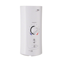
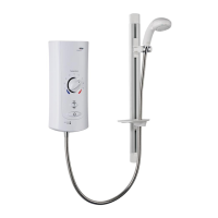
1.2. The Mira Advance is suitable for installation within the shower area and must be
positioned over a water catchment area with the controls at a convenient height
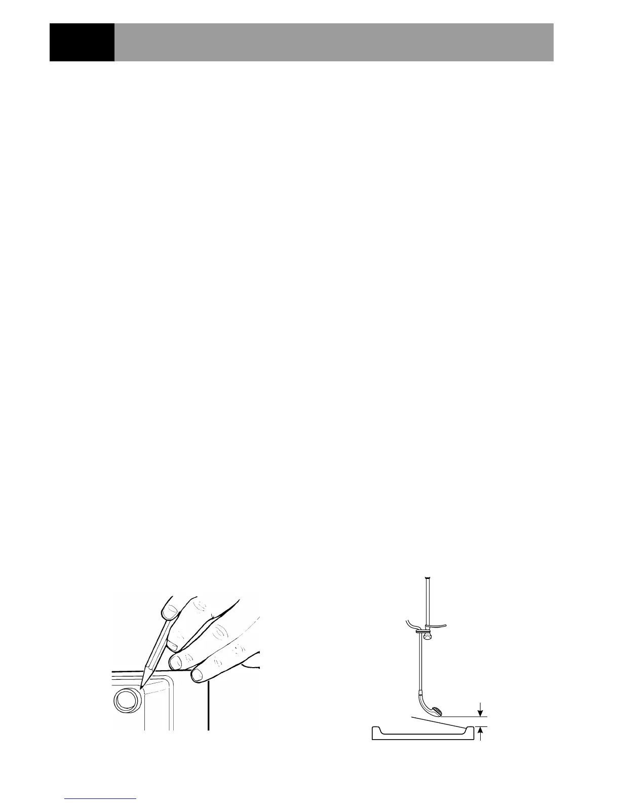
for the user. The shower fitting should be positioned so that it discharges down
the centre line of the bath, or across the opening of a shower cubicle, and must
be directed away from the Mira Advance.
1.3.1.3.
1.3.1.3.
1.3. The Mira Advance is fitted with an inlet connector assembly that is designed to
accept plumbing supplies from the top, bottom or back. The water supply can be
fed with 15 mm pipe or 10 mm microbore pipe, suitably reduced into the inlet
connector assembly. If 10 mm microbore is used, then an allowance for
increased pressure loss must be made to ensure that the minimum maintained
inlet pressure is achieved (see note above).
1.4.1.4.
1.4.1.4.
1.4. The Mira Advance must be fitted
ONTOONTO
ONTOONTO
ONTO the finished wall surface i.e. on top
of the tiles.
DO NOTDO NOT
DO NOTDO NOT
DO NOT block the air ventilation gaps around the sides of the
unit, either by tiling up to the sides of the unit or by using a sealant around
the case (Small pillars moulded on to the back of the case allow air
circulation). This Mira Advance is designed to be ventilated. Failure to do
this may cause product failure (Refer to Figure 1).
1.5.1.5.
1.5.1.5.
1.5. Use only the inlet connector assembly supplied with the Mira Advance, do not
use any other types of fitting.
Section
6
Installation RequirementsInstallation Requirements
Installation RequirementsInstallation Requirements
Installation Requirements
Figure 1Figure 1
Figure 1Figure 1
Figure 1
Figure 2Figure 2
Figure 2Figure 2
Figure 2
Spill-over Level
25 mm minimum
 Loading...