16. Fit the shower ttings, refer to your shower
fittings installation and user guide for
instructions.
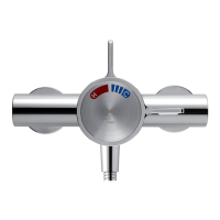
Note! For high pressure systems (above
0.5 bar) make sure that the ow regulator
(supplied) is tted inside the outlet nipple (refer
to illustration).
Important! The tting of this ow regulator will
invalidate any TMV2 or TMV3 compliance due
to the minimum ow rate requirements. Do
not t the ow regulator in TMV2 and TMV3
applications.
Flow Regulator
17. Turn on the hot and cold water supplies and
check for leaks.
18.
Before using the shower, refer to section:
‘Commissioning’.
Built-in Thermostatic Mixers
Solid Wall or Stud Partition Fixing
using Rear Mountings
1. Determine the route for the hot and cold
supply pipework and for the outlet pipework.
When connecting to BIV Shower Fittings it is
recommended that the outlet be positioned
above and to one side of the mixer. This is to
prevent the exible hose from obstructing the
shower controls.
2.
Remove the two shroud screws (retain for later
use) and remove the building-in shroud from
the mixer.
3.
Determine the position of the mixer and draw
around the building-in shroud.
4. Mark the routes for the hot and cold supply
pipework (Hot - Left, Cold - Right) and for
the outlet pipework.
Note! (if applicable) The outlet elbow should
be sited above the mixer and on the right or
left, as site dictates.
Outlet Pipe BIR
Outlet Pipe BIV Outlet Pipe BIV
Cold InletHot Inlet
Thermostatic
Mixer
Alternative Pipe
Layouts