11. Insert the wall plugs and attach the mixer to
the wall with the screws provided.
Note! For stud partition installations alternative
xings may be required (not supplied) to x the
mixer to the rear face of the wall cavity or to a
timber noggin.
Screws
Outlet Pipe to
Fittings
Hot Supply
Cold Supply
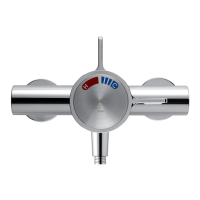
12. Remove the two shroud screws (retain for later
use) and remove the building-in shroud from
the mixer.
13.
Make sure that the olives are tted, connect
the hot and cold supply pipes and tighten the
compression nuts.
14. Connect the outlet pipework and install the
RAC assembly or BIR assembly, before
continuing with the installation of the mixing
valve.
RAC assembly, go to section: ‘Installation,
RAC Assembly’.
BIR assembly, refer to your shower ttings
installation and user guide then continue with
instruction 15.
15.
Turn on the water supplies and check for
leaks.
16.
Ret the building-in shroud to the mixer using
the two shroud screws removed earlier.
17.
Using the ‘Finished Wall Indicator’ on the
building-in shroud as a guide, nish the wall,
e.g. tiles.
Caution! Make sure that the nished wall
is within the maximum and minimum limits
and to an even depth (no greater than 2 mm
variation) or the control components will not
t correctly.
Minimum
nished wall
surface
Maximum
nished wall
surface
18. Remove the two shroud screws (retain for later
use) and remove the building-in shroud.
19. Fit the concealing plate and control assembly,
refer to section: ‘Control Assembly’.