9. Mark the positions of the two RAC backplate
xing holes and drill two Ø5.5 mm holes.
Caution! Make sure that you do not drill into
pipework in the wall.
10. Hold the RAC wallplate in position on the
rear of the partition, insert the two backplate
screws and secure the RAC backplate to the
wallplate. Make sure that the foam seal abuts
the nished wall surface. Go to instruction
22.
RAC Backplate
Backplate
Screws
11. Loosely attach the RAC backplate to the RAC
wallplate, using the two backplate screws
provided.
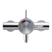
12.
Place the RAC backplate/wallplate assembly
over the outlet pipe with the arrow pointing
vertically up. The screw holes should be at
40° to the horizontal.
13.
Mark the positions of the two RAC wallplate
xing holes.
Wallplate
RAC Backplate
Backplate Screws
Arrow
40°
14. Remove the assembly from the wall and
separate the backplate from the wallplate.
15. For solid walls drill two Ø6 mm holes for the
wall plugs. For other types of wall structure
alternative fixings may be required (not
supplied). If necessary, make a recess 6 mm
deep to accept the wallplate for ush tting of
the outlet to the wall surface.
Caution! Make sure that you do not drill into
pipework in the wall.
16. Fit the two wall plugs supplied and secure
the wallplate to the wall with the two wallplate
screws.
17. Make sure that there is clearance behind the
wallplate and temporarily t the two backplate
screws into the wallplate. This will prevent
the xing holes from becoming blocked with
plaster or grout.
18.
Secure the building-in shroud to the mixing
valve using the two shroud screws removed
earlier.
19.
Using the building-in shroud as a guide, nish
the wall, e.g. tiles.
Caution! Make sure that the nished wall
is within the maximum and minimum limits
and to an even depth (no greater than 2 mm
variation) or the control components will not t
correctly.
Minimum
nished wall
surface
Maximum
nished wall
surface
20. Remove the two backplate screws, the two
building-in shroud screws (retain for later use)
and the building-in shroud.
21. Place the backplate over the outlet pipe with
the arrow pointing vertically up and tighten the
two backplate screws. Make sure that the foam
seal abuts the nished wall surface.