FA-106 Installation and Operation Manual
9
Wiring Tables and Information
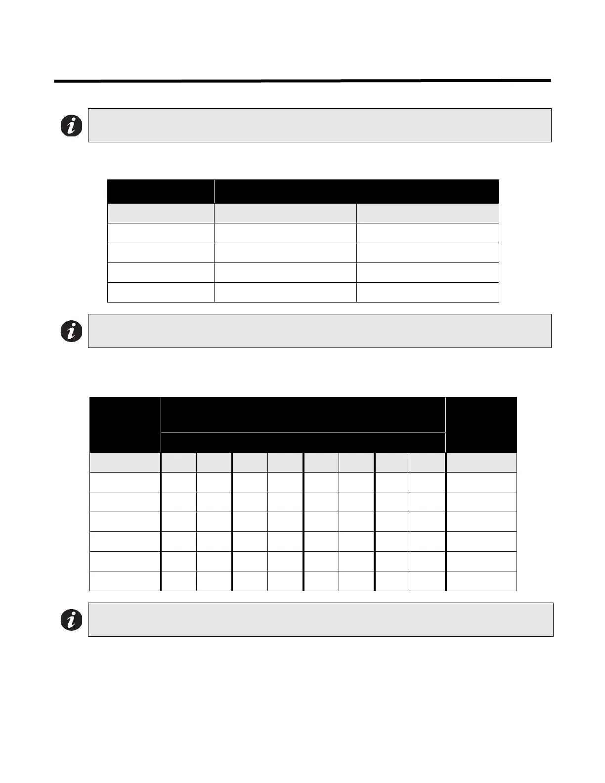
Table 1: Wiring table for detection zone
Table 2: Wiring table for bells and horns
Signal circuits are rated for 1.25 amperes each.
Note: The panel must be wired by a certified electrician in accordance with CEC part 1, section 32 “Fire
alarm systems, fire pumps, and carbon monoxide alarms”.
Wire Gauge Maximum Wiring Run to Last Device (ELR)
(AWG) ft. m
18 7560 2300
16 12000 3600
14 19000 5800
12 30400 9200
Note: Maximum loop resistance should not exceed 100 ohms.
Total Signal
Load
Maximum Wiring Run to Last Device (ELR)
Max Loop
Resistance
18AWG 16AWG 14AWG 12AWG 0hms
Amperes ft. m ft. m ft. m ft. m Ohms
0.06 2350 716 3750 1143 6000 1829 8500 2591 30
0.12 1180 360 1850 567 3000 915 4250 1296 15
0.30 470 143 750 229 1200 366 1900 579 6
0.60 235 71 375 114 600 183 850 259 3
0.90 156 47 250 76 400 122 570 174 2
1.25 109 33 171 52 277 84 450 137 1.4
Note: Maximum voltage drop should not exceed 1.8 volts.