70
Configuration with the CFG-300 LCD Service Tool
11.3.5 Command Menu/FA-300 Config-->Correlation
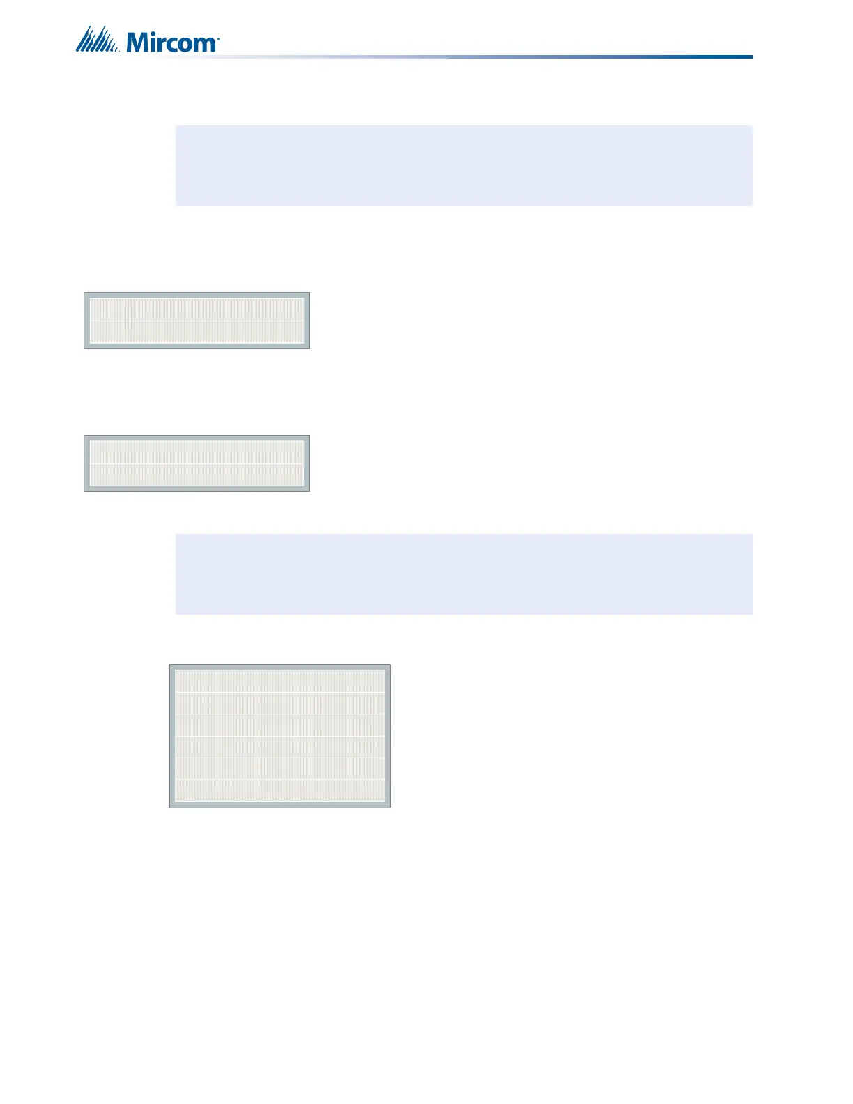
11.3.6 Command Menu/FA-300 Config-->Inp Zone Label
Use the buttons described below for entering messages. These buttons are alternate functions
of bypass switches and are physically located in the same position as described following.
Note: Refer to 11.2.1 Using the Keypad to Program the FA-300 on page 61 for detailed
instructions on making menu selections.
Command Menu/FA-300 Config/Correlation
1.Correlation
|
|
|
12.
[X] NAC-1 ->Default
[X] NAC-2 ->Default
[X] NAC-3 ->Default
[X] NAC-4 ->Default
Use this menu to correlate
initiating circuits to
indicating circuits. By
default all the initiating
circuits are correlated to all
the indicating circuits.
Note: Refer to 11.2.1 Using the Keypad to Program the FA-300 on page 61 for detailed
instructions on making menu selections.
1 Zone-1
2 Zone-2
--
--
Initiating Zone
12 Zone12