Installation Instructions
2
Installation Instructions
Note that the RAM-1032(TZ) and the RAM-1016(TZ) are supplied with the NP-680 laser printable
label sheet. Column 1A or 1B (English or French) is selected for either a 2-stage or 1-stage system
respectively. Discard column three and fill out the last four columns with the blanks after they have
been printed. The RAX-1048(TZ) is supplied with the NP-681 blank laser printable label sheet.
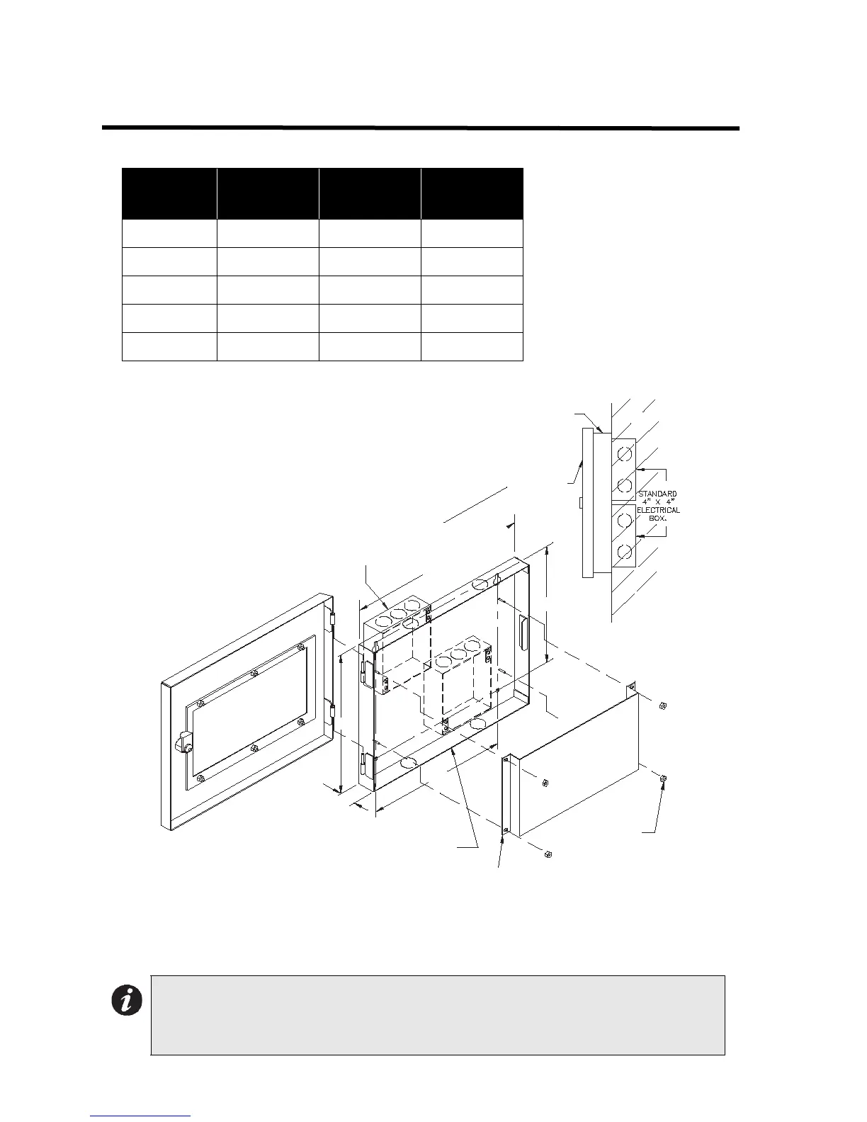
BACKBOX
HEIGHT
H
MOUNTING
A(IN.)
MOUNTING
B(IN.)
BB-1001 9.0” 9.95” 7.5”
BB-1002 18.0” 9.95” 16.5”
BB-1003 26.5” 9.95” 24.9”
BB-1008 33.0” 20.9” 35.2”
BB-1012 45.0” 20.9” 52.0”
Note: The RA-1000 normally displays Initiating Circuit Status (no individual circuit
troubles); however, models RAM-1016TZ, RAM-1032TZ, and RAX-1048TZ will
allow individual circuit trouble indication. Indicating and Relay Circuits are not
remotely displayed. For more details, see the Fire Alarm Control Panel manual.
B
WALL
ANNUNCIATOR CHASSIS
BB-1001 BACKBOX IS SHOWN
12.75"
H
1.2"
A
BACKB OX C AN BE MOUNTED
WITH STANDARD 4" X 4"
ELECTRICAL BOXES
DOOR
#6-32
HEXNUTS
BACKB OX

 Loading...


