RA-1000 Remote Annunciator Wiring and Instruction Manual
3
Wiring Instructions
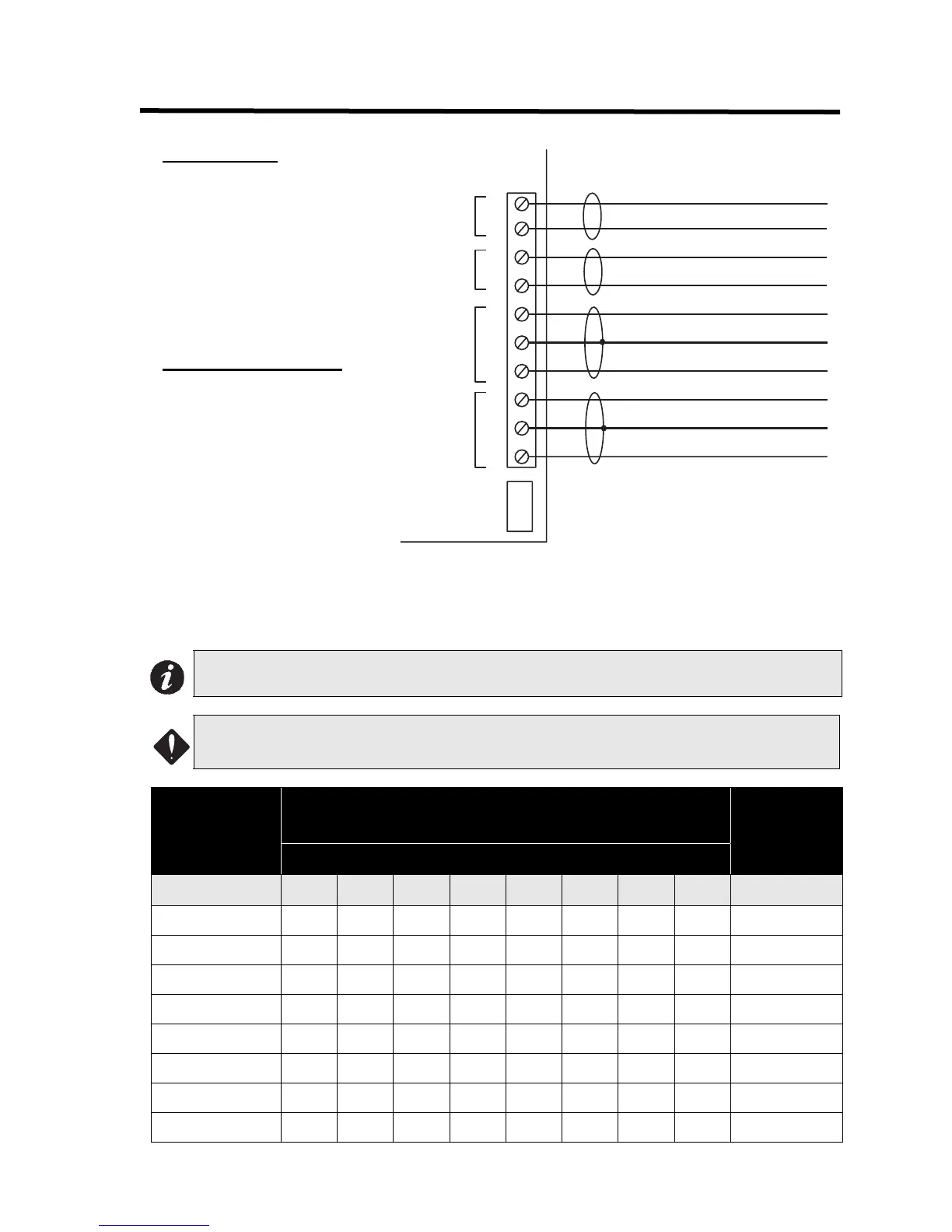
RS-485 WIRING
The RS-485 wiring to the RAM-
1032(TZ) and RAM-1016(TZ)
Module is recommended to be
twisted shielded pair as shown in
the diagram. The wire gauge may
be:
• 22 AWG up to 2000 ft.
• 20 AWG up to 4000 ft.
24V DC POWER WIRING
The RS-485 wiring from the fire
alarm control panel to the
annunciator(s) must be point-to-
point from the fire alarm panel to
the first annunciator, then to the
next annunciator, and so on. No
star wiring or T-tapping is allowed.
Each RAM-1032(TZ) and RAM-
1016 Annunciator Module has a
120 ohm end-of-line resistor on its
RS-485 output terminals. This is removed on all except the last wired module.
The 24 VDC field wiring needs to be of an appropriate gauge for the number of annunciators and the total
wiring run length. Use the Current Drain for Battery Calculations on page 8 to calculate the maximum current
for all annunciators summed together
.
Note: All circuits are power limited and must use type FPL, FPLR, or FPLP power limited cable.
ATTENTION: Accidentally connecting any of the 24 VDC wires to the RS-485 wiring will result in
damage to the annunciator and/or to the fire alarm control panel to which it is connected.
Max for all
Annunciators
Maximum Wiring Run to Last Annunciator
Max Loop
Resistance
18AWG 16AWG 14AWG 12AWG 0hms
Amperes ft. m ft. m ft. m ft. m Ohms
0.06 2350 716 3750 1143 6000 1829 8500 2591 30
0.12 1180 360 1850 567 3000 915 4250 1296 15
0.30 470 143 750 229 1200 366 1900 579 6
0.60 235 71 375 114 600 183 850 259 3
0.90 156 47 250 76 400 122 570 174 2
1.20 118 36 185 56 300 91 425 129 1.5
1.50 94 29 150 46 240 73 343 105 1.2
1.70 78 24 125 38 200 61 285 87 1.0
+
24 VDC
INPUT
-
S
S
-
+
-
+
-
+
P11
RS-485
INPUT
RS-485
OUTPUT
24 VDC
OUTPUT
24 VDC POWER FROM FIRE ALARM CONTROL
PANEL OR PREVIOUS ANNUNCIATOR
24 VDC POWER TO
NEXT ANNUNCIATOR
RS-485 TO NEXT ANNUNCIATOR
(TWISTED SHIELDED PAIR)
RS-485 FROM FIRE ALARM OR PREVIOUS
ANNUNCIATOR (TWISTED SHIELDED PAIR)

 Loading...


