50 TX3 Telephone Access System Installation and Operation Manual
Lobby Control Unit Setup
4.5 IP Module
The IP Module connects the Lobby Control Unit to an Ethernet TCP/IP network.
The IP Module ribbon cable connects to the P5 connector on the controller board
(see figure 20). This allows you to configure and monitor the TX3 devices on
your system using a computer and an Ethernet connection.
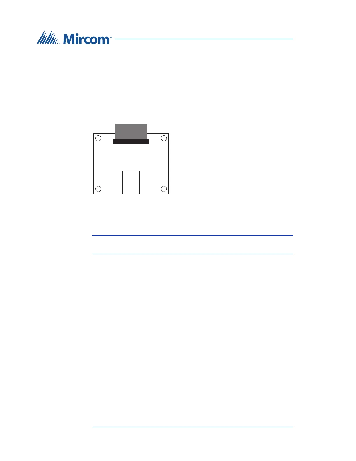
The IP Module has an RJ-45 connector that connects to the Ethernet network
using a standard Ethernet cable as shown in figure 28.
Figure 28. IP Module Data and Ethernet Connectors
For a description on how to install the IP Module, see LT-1161 TX3-IP IP
Module Installation Instructions.
Note: The TX3-IP IP Module can only be installed on models that end
with “-A” or “-B” or “-C” (for example, TX3-ER-8-A).
4.6 RS-485 Add-on Module
The RS-485 Add-on Module converts RS-485 signals to USB and is part of the
USB to RS-485 Adapter (TX3-USB-AD). The RS-485 Add-on Module ribbon
cable connects to the P4 connector on the controller board. See figure 20.
IP Module Ribbon Cable
RJ-45
Connector