4MELFA-BASIC V
Coordinate system description of the robot 4-153
2) Automatic operation
Travel command permits you to set robot motion during the removal or transfer of processed work by
specifying approach/pullout distance settings. Approach or pullout takes place in the direction of the Z
axis of the robot's tool coordinate system.
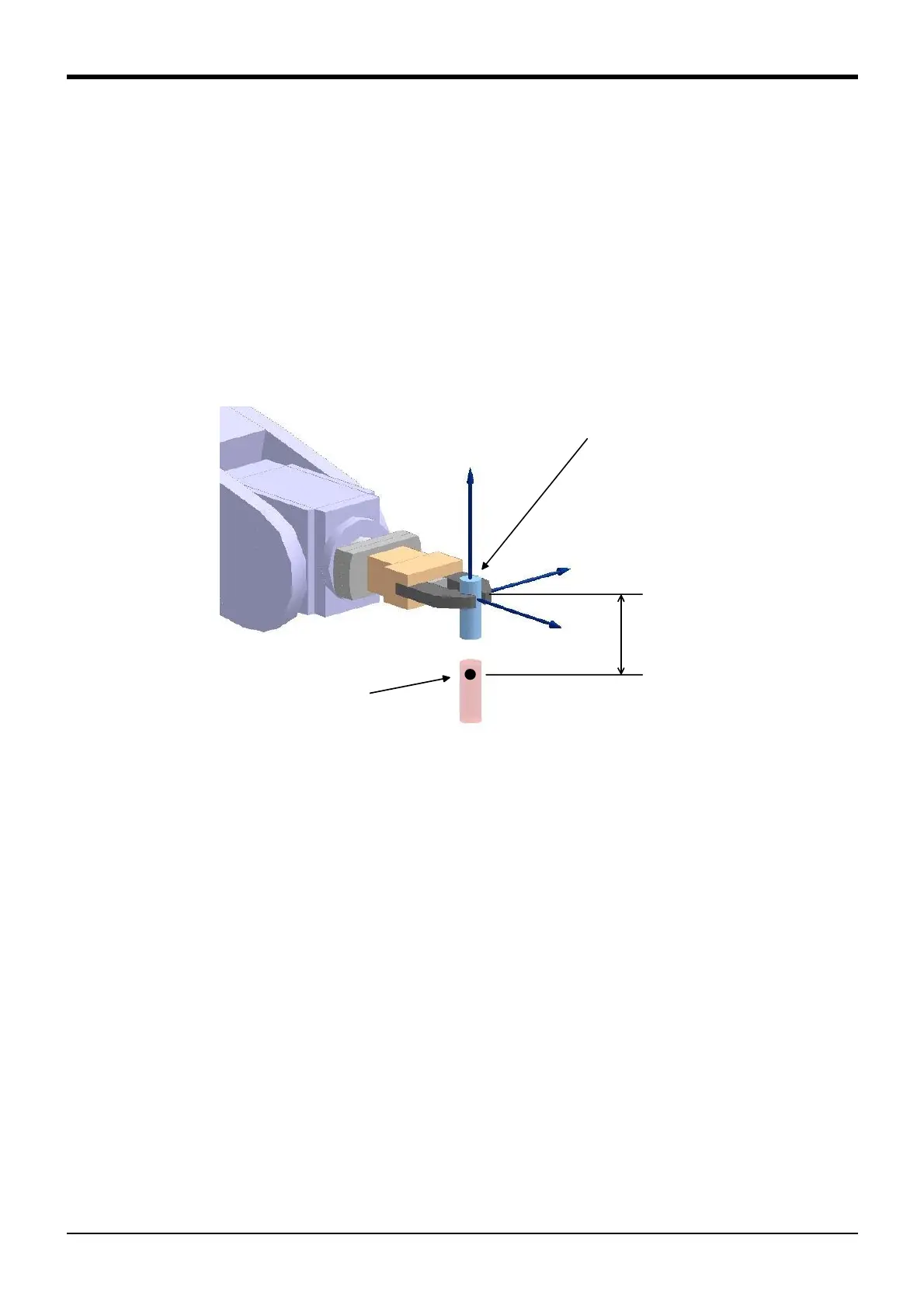
To move the robot hand to a point 50mm over the work transfer position as shown in Fig. 4-10, the fol-
lowing indication is used:
Mov P1,50
This means that the robot hand should move +50mm in the direction of the Z axis at P1 (tool
coordinate system).
Setting the direction of the Z axis of the tool coordinate system to suit the orientation of work being pro-
cess and/or the operating condition of the robot leads to an improved workability.
In the example shown in Fig. 4-10, because the robot hand is oriented laterally to insert or remove the
work, the direction of the Z axis of the tool coordinate system is chosen to agree with the orientation of
the work.
Fig.4-10:Approach/pullout motion
Making tool data settings will come in useful when you have to make changes to the posture of your work
as in work phasing, as well.
To achieve work phasing by turning the work on its center axis as shown in Fig. 4-11, the following indica-
tion is used:
Mov P1*(0,0,0,0,0,45)
"*(0, 0, 0, 0, 0, 45)" means that a position calculation should be carried out at "*" and that C out of (X, Y, Z,
A, B, C) should be rotated 45 degree. As C represents a rotation on the Z axis, the robot comes to rotate 45
degree on the Z axis (Zt axis of tool coordinate system) at P1.
Work
Work transfer
position
(position: P1)
 Loading...


