234
APPX
Appendix 1 Calculating Safety Response Time for System Configured with a Safety CPU
APPENDICES
Appendix 1 Calculating Safety Response Time for
System Configured with a Safety CPU
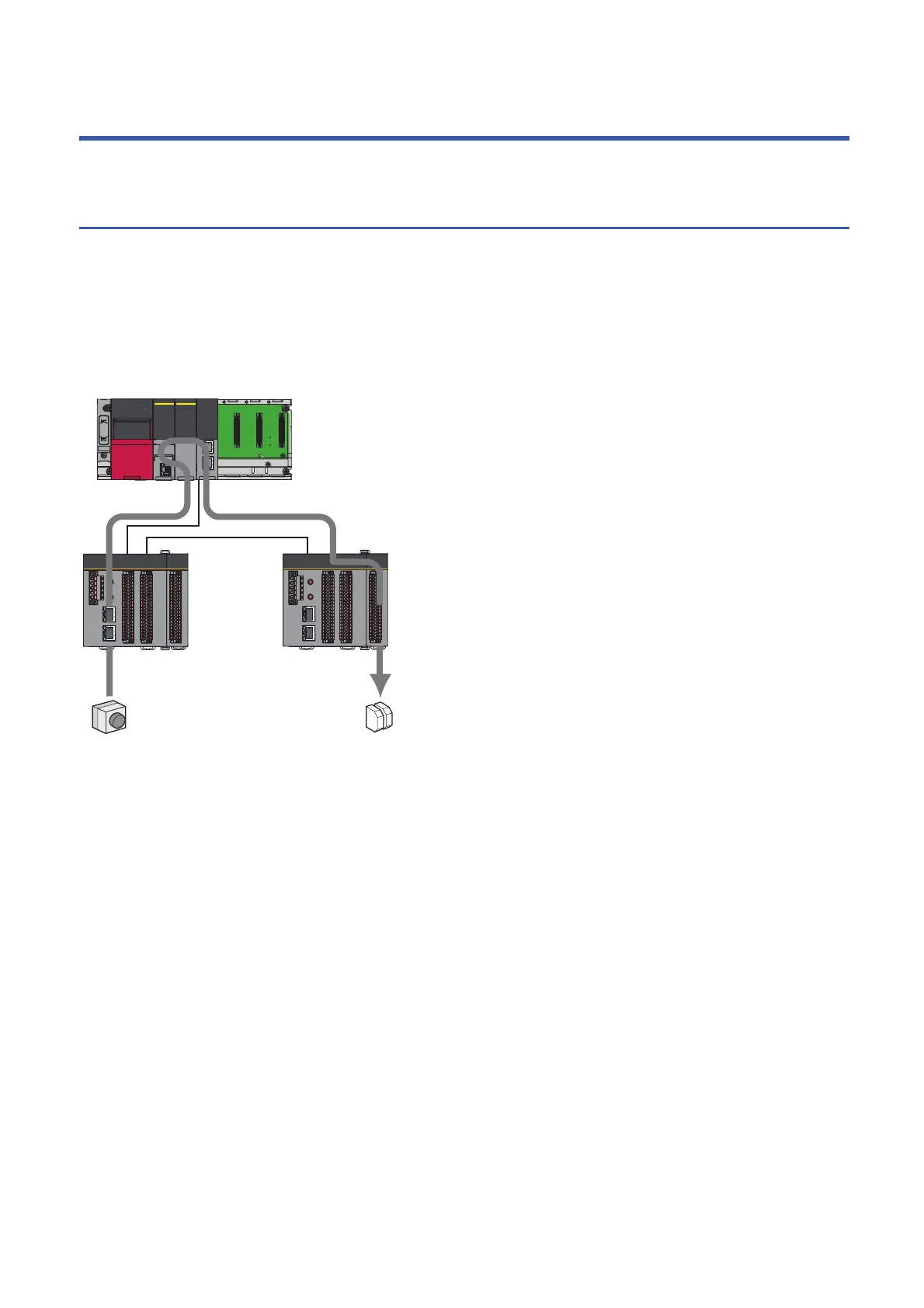
This section describes the maximum value of safety response time for a system configured with a Safety CPU. For systems
connected to multiple Safety CPUs, refer to Page 242 Calculating Safety Response Time for System Connected to Multiple
Safety CPUs. The following example connects input equipment and output equipment to different safety remote I/O modules,
however, even cases where connected to same safety remote I/O module, calculation of safety response time can be
performed using method described here. As explained as a line topology, however, calculation is possible by methods
described in this chapter regardless the connection methods such as line topology, star topology, or ring topology.
MELSEC iQ-R CC-Link IE Field Network User's Manual (Application)
(b)
(a)
(c)
Emergency
stop switch
Safety
relay

 Loading...


