242
APPX
Appendix 2 Calculating Safety Response Time for System Connected to Multiple Safety CPUs
Appendix 2 Calculating Safety Response Time for
System Connected to Multiple Safety
CPUs
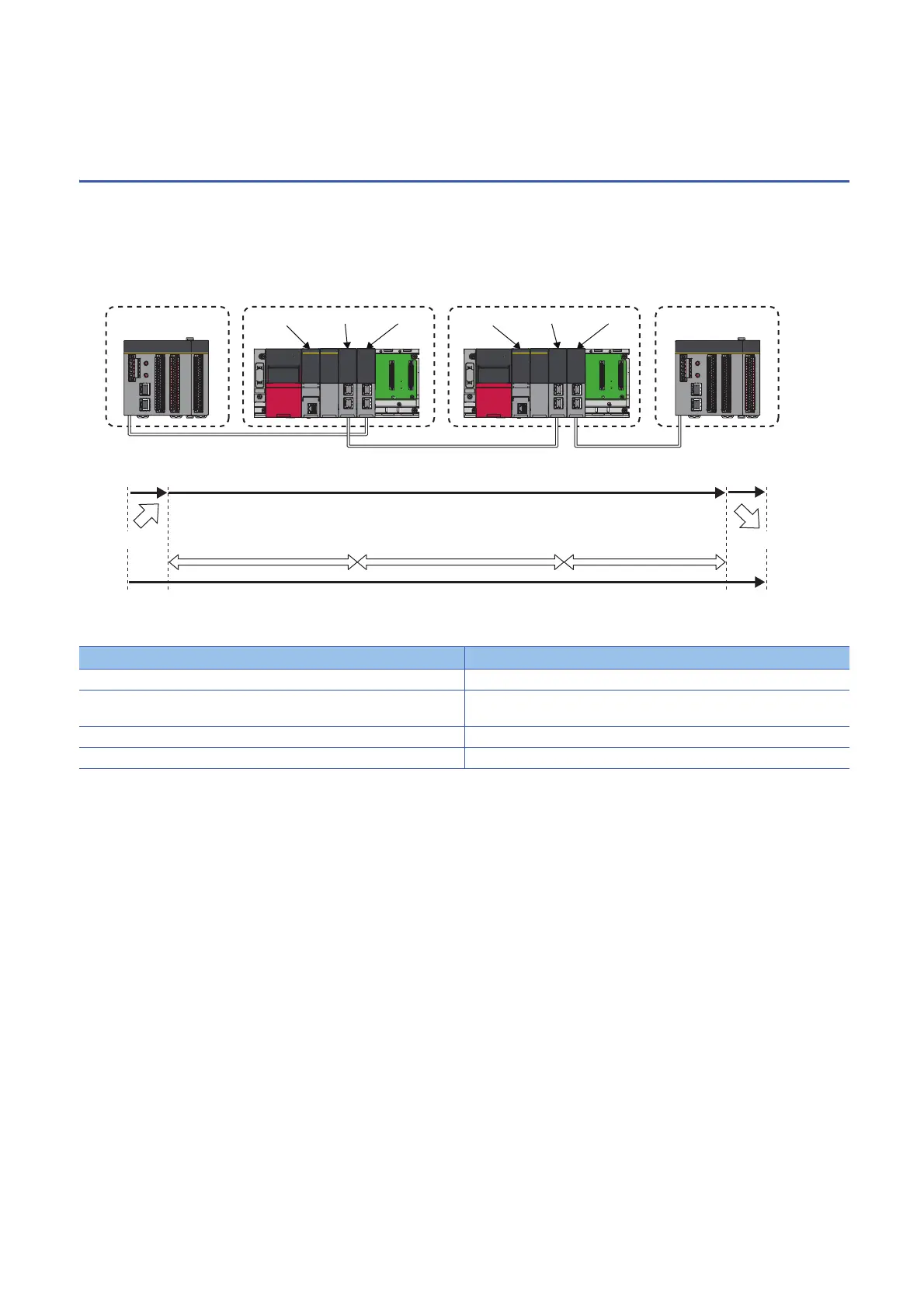
This section describes the maximum value of safety response time for a system connected to multiple Safety CPUs using the
CC-Link IE Field Network. As described as a line topology, however, calculation is possible by methods described here
regardless of the connection methods such as line topology, star topology, or ring topology. For normal values, refer to the
following.
MELSEC iQ-R CC-Link IE Field Network User's Manual (Application)
The maximum value of safety response time will be the sum of (a) to (c) of the following.
Explanations of symbols used for this chapter
• LS (1): CC-Link IE Field Network link scan time of Network Number 1
• LS (2): CC-Link IE Field Network link scan time of Network Number 2
• LS (3): CC-Link IE Field Network link scan time of Network Number 3
• DT1, DT2: Response time of a sensor or output-target control device. Check and add the following response time of the
device used.
Item Maximum value
(a) Input device response time DT1
(b) Safety data transmission time (maximum value) Transmission time of CC-Link IE Field Network from safety input to safety
output
(c) Output device response time DT2
To t al DT1 + DT2 + Safety data transmission time (maximum value)
Safety remote I/O station (1)
Network No.2
Network No.1 Network No.3
Safety CPU (1) Master station Master station
Safety remote I/O station (2)
Safety input
Safety response time
(1) CC-Link IE Field Network
input transmission time
(2) CC-Link IE Field Network
transmission time
(3) CC-Link IE Field Network
output transmission time
Safety data transmission time
Safety output
Input device
response time
Output device
response time
Safety CPU (2) Local station Master station

 Loading...


