72
5 SAFETY APPLICATION CONFIGURATION EXAMPLES
5.1 System Configured by a Safety CPU
Relationship between devices in the Safety CPU and remote
inputs/outputs
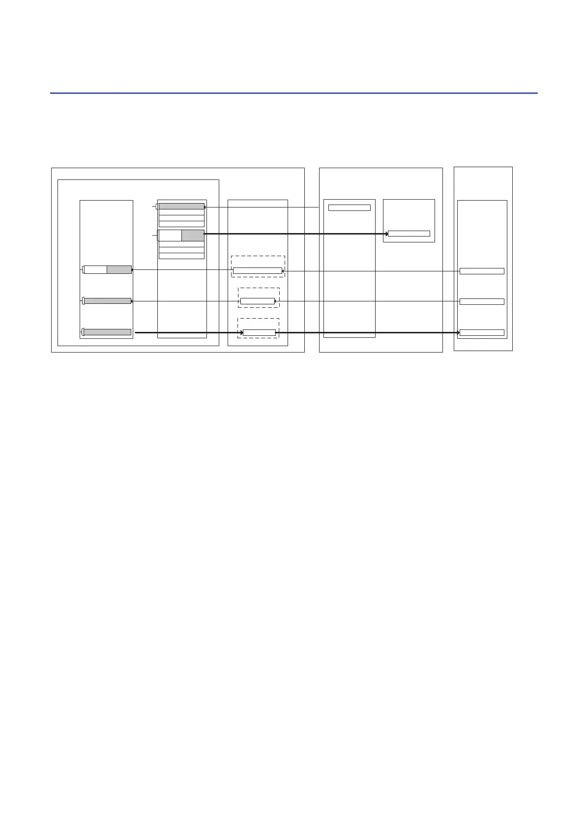
The following shows the relationship between the Safety CPU device, the inputs/outputs of safety remote I/O module, and the
standard remote I/O module according to the settings on Page 58 Parameter settings of CC-Link IE Field Network. Use
devices in shaded areas in the program.
The system uses 16 points each of the RWr/RWw to communicate with the safety remote I/O module. Set 16 points each of
the RWr/RWw according to Page 58 Parameter settings of CC-Link IE Field Network. Do not read/write data from/to the RWr/
RWw to be used by the system. Writing data may cause malfunction of the safety programmable controller.
For details, refer to the following.
CC-Link IE Field Network Remote I/O Module (With Safety Functions) User's Manual
XF-X0
0013-0000
RWr
0013-0000
RWw
X1F-X0
Y7-Y0
RWr
RWw
0023-0010
0023-0010
RX005F-RX0050
RX
X10F-100
X1F-X110
W0113-W0100
W0213-W0200
NZ2GFSS2-32D NZ2EXSS2-8TE NZ2GF2B1-16D
Safety CPU
CC-Link IE Field Network
master/local module
Main module Extension module
Safety remote I/O module
(station No.1)
CCIEF remote (1): SR_IO1
SA\X1F - SA\X0
SA\X3F - SA\X20
SA\Y3F - SA\Y20
Station
No.1
Station
No.1
SA\X5F - SA\X40
SA\X7F - SA\X60
SA\Y5F - SA\Y40
SA\Y7F - SA\Y60
SA\Y7 -
SA\Y0
SA\Y1F -
SA\Y8
Standard remote I/O module
(station No.2)
CCIEF remote (2): R_IO2
Main module
Station
No.2
Station
No.2
Station
No.2
For safety programsFor standard programs

 Loading...


