Do you have a question about the Mitsubishi Electric Melservo MR-J3-A and is the answer not in the manual?
| Type | AC Servo Amplifier |
|---|---|
| Manufacturer | Mitsubishi Electric |
| Number of Axes | 1 |
| Communication Interface | SSCNET III |
| Certifications | CE, UL, cUL |
| Series | MR-J3 |
| Output Power | 0.1kW to 15kW |
| Cooling Method | Natural Cooling |
| Protection Features | Overcurrent, Overvoltage, Overload, Overheat, Encoder Error |
| Ambient Operating Temperature | 0°C to +55°C |
| Input Voltage | 3-phase 200V to 230V AC |
| Ambient Operating Humidity | 10% to 90% RH (non-condensing) |
Explains safety levels (Warning, Caution) and diagrammatic symbols used.
Covers precautions for transporting and installing servo amplifiers and motors.
Details on correct and secure wiring procedures for the servo system.
Procedures for test run adjustments to ensure proper operation.
Details on how to use the servo amplifier, including emergency stop and braking.
Procedures for handling hazardous conditions and alarms.
Lists precautions for compliance with EC directives, including compatible models and configuration.
Instructions for proper grounding of the servo amplifier.
Guidelines for wiring servo amplifier cables correctly.
Details the time for capacitor discharge after power-off for safety.
Precautions for wiring protection according to electrical codes.
Overview of the MELSERVO-J3 series features and improvements over J2-Super series.
Shows the functional block diagram of the servo amplifier.
Lists standard specifications for 200VAC and 100VAC classes.
Lists servo functions, descriptions, control modes, and reference sections.
Table of compatible servo amplifiers and motors, including those with electromagnetic brakes.
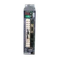
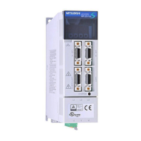
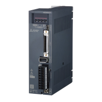
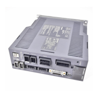
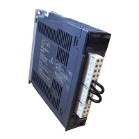
Details the physical structure and parts identification of the servo amplifier.
Identifies parts of the MR-J3-100A or less servo amplifier.
Instructions for safely removing and reinstalling the front cover.
Shows configuration diagrams for auxiliary equipment.
Specifies installation direction and clearance requirements for servo amplifiers.
Precautions to prevent foreign materials from entering the servo amplifier.
Guidelines for managing cable stress to prevent damage.
Periodic inspection checks recommended for the servo amplifier.
Identifies parts with limited service lives and replacement recommendations.
Shows wiring diagrams for power supply connections to the servo amplifier.
Shows I/O signal connection examples for different control modes.
Explains power supply system signals and connections.
Shows connector layouts and signal assignments.
Details I/O signals and their assignments in different control modes.
Provides detailed explanations of signals.
Shows timing charts for various alarm occurrences.
Instructions on connecting shielded cables and ground plates.
Details on connecting the servo amplifier and servo motor, including warnings.
Safety precautions and setting for using servo motors with electromagnetic brakes.
Instructions for proper grounding of servo amplifiers and motors.
Procedure for the initial power-on and startup.
Specific startup procedures for position control mode.
Specific startup procedures for speed control mode.
Specific startup procedures for torque control mode.
Basic parameters for position control mode, including control mode, auto tuning, and torque limits.
Lists parameters for gain and filter adjustments.
Lists parameters for extension settings like acceleration/deceleration time, speed limits.
Lists parameters for configuring I/O signals.
Describes how the servo status is displayed on the LED.
Explains various diagnostic modes available on the servo amplifier.
Displays current alarms, alarm history, and parameter errors.
Describes how to access and change parameters.
Confirms ON/OFF states of digital I/O signals.
Allows forcing output signals ON/OFF for wiring checks.
Explains the test operation mode for confirming servo operation.
Explains different methods for adjusting servo gains.
Explains the real-time auto tuning function for optimizing gains.
Simple manual gain adjustment using three parameters.
Used for matching position loop gains of multiple axes for interpolation operation.
Explains the adaptive filter function for suppressing mechanical vibration.
Explains the notch filter for suppressing mechanical resonance.
Function to further suppress machine end vibration.
Explains the low-pass filter for preventing high-frequency resonance.
Allows changing gains during rotation or stop, or via external signal.
Lists alarms and warnings, their codes, names, and causes.
Provides actions to take for various alarm conditions.
Lists remedies for warning conditions.
Provides outline drawings and dimensions for various servo amplifier models.
Details connector types and dimensions for CN1.
Shows overload protection curves for various servo amplifiers.
Table of power supply capacities and generated heat for servo amplifiers.
Explains dynamic brake operation and time constants.
Graph showing encoder cable flexing life.
Table indicating inrush currents for various servo amplifiers.
Lists available cables and connectors for the servo system.
Lists combinations of regenerative options and servo amplifiers with power values.
Details brake units, resistor units, and their applications.
Explains the use and selection of power regeneration converters.
Explains the use and selection of common power regeneration converters.
Information on dynamic brake units and their selection.
Details the junction terminal block and its usage.
Introduces the MR Configurator software and its functions.
Information about the battery unit for absolute position detection.
Details the heat sink attachment for MR-J3-11KA(4) to 22KA(4).
Shows recommended wires for power supply wiring and tables for wire sizes.
Lists recommended no-fuse breakers, fuses, and magnetic contactors.
Explains the function and selection of DC reactors.
Explains how power factor improving reactors work and their benefits.
General techniques for reducing external and radiated noise.
Explains how to select and install leakage current breakers.
Recommends EMC filters for compliance with EN standards.
Explains configuration for single-axis and multidrop communication.
Details communication specifications like baud rate and transfer protocol.
Details the communication protocol, including data transmission configurations.
Lists commands and data numbers for various operations.
Provides detailed explanations for commands.
Explains how to specify and read parameter groups.
Reads ON/OFF states of input and output devices.
Explains how to test input devices ON/OFF.
Explains how to use test operation modes like JOG, Positioning, Motorless.
Reading and clearing alarm history.
Reading and clearing the current alarm.
Commands for reading servo motor absolute position and software version.
Provides an overview of the absolute position detection system.
Lists specifications for the absolute position detection system.
Provides procedures and precautions for battery installation.
Shows the standard connection diagram for absolute position detection.
Explains signals related to ABS transfer mode and home position setting.
Outlines the steps for starting up the absolute position detection system.
Explains the protocol for transferring absolute position data.
Provides examples of using the absolute position system with PLCs.
Lists errors related to absolute position data transfer.
Details the system for ABS transfer via serial communication.
How to confirm absolute position data using MR Configurator.
Lists basic and gain/filter parameters.
Provides signal layout diagrams for CN1 in different control modes.
Block diagram illustrating status display items.
Lists current and RoHS compatible connector sets.