EasyManuals Logo

Mitsubishi Electric -MR-CV User Manual

Mitsubishi Electric -MR-CV
120 pages
To Next Page IconTo Next Page
To Previous Page IconTo Previous Page
Page #20 background imageLoading...
Page #20 background image
18
4 STRUCTURE (PARTS IDENTIFICATION)
4.1 Parts identification
4 STRUCTURE (PARTS IDENTIFICATION)
4.1 Parts identification
MR-CV18K(4) or lower
This diagram shows the terminal cover in the open position. For how to open and close the terminal cover, refer to the
following.
Page 24 Opening and closing the terminal cover
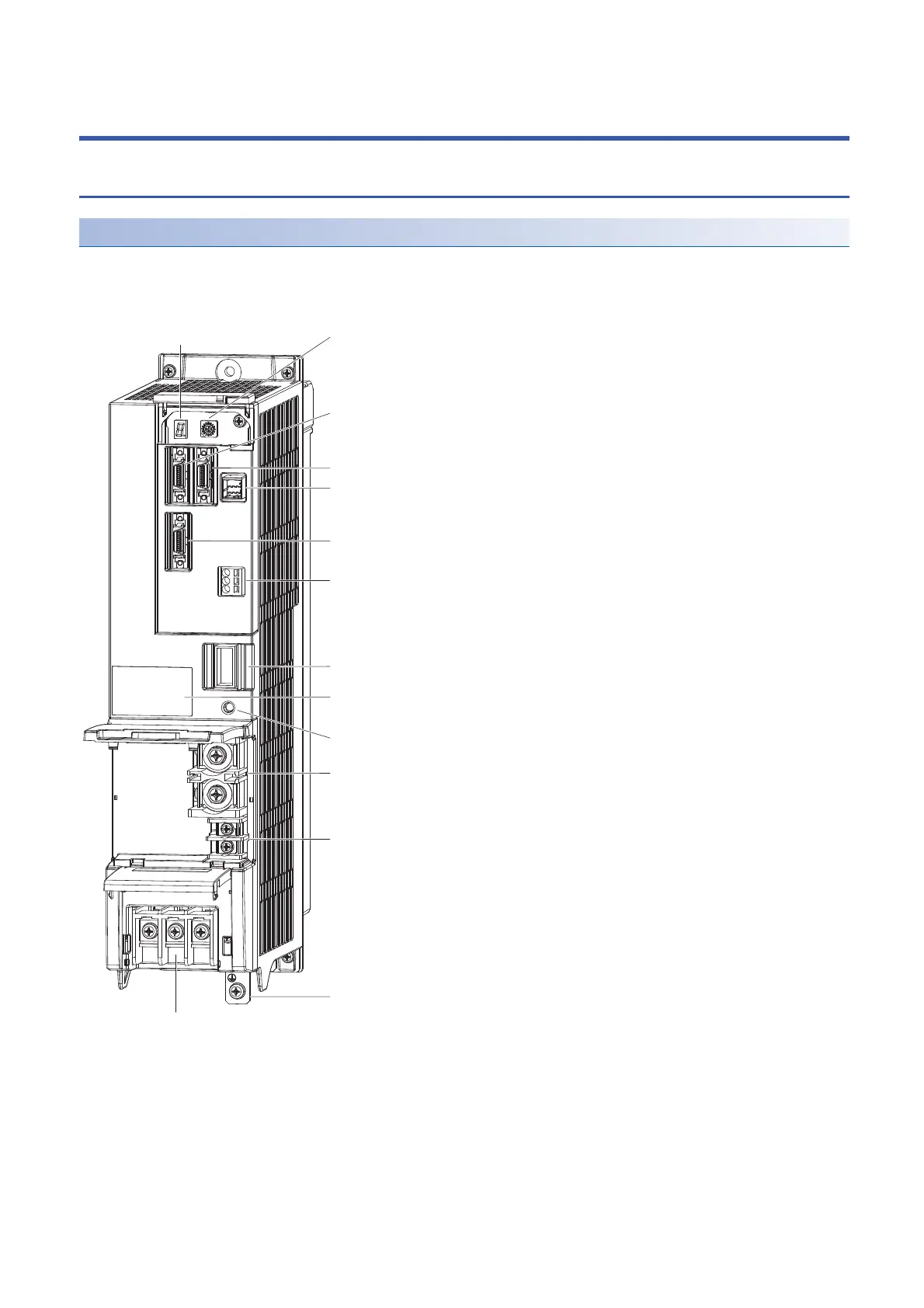
(1) Display section (2) Rotary switch for converter setting (SW1)
(12) Main circuit terminal block (TE1)
(5) Manufacturer setting connector (CN41)
(4) Manufacturer setting connector (CN9)
(14) Rating plate
(11) Alarm output connector (CN25)
(7) Magnetic contactor control connector (CN23)
(10) Control circuit terminal L11/L21 (TE3)
(13) Protective earth (PE) terminal
(9) L+/L- terminal (TE2)
(8) Charge light
(6) I/O signal connector (CN24)
(3) Protection coordination connector (CN4)

Table of Contents

Questions and Answers:

Question and Answer IconNeed help?

Do you have a question about the Mitsubishi Electric -MR-CV and is the answer not in the manual?

Mitsubishi Electric -MR-CV Specifications

General IconGeneral
BrandMitsubishi Electric
Model-MR-CV
CategoryController
LanguageEnglish

Related product manuals