EasyManua.ls Logo

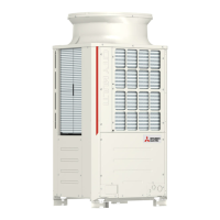
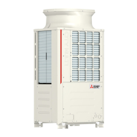
Mitsubishi Electric PUHY-P250 User Manual

Mitsubishi Electric PUHY-P250
354 pages
To Next Page IconTo Next Page
Page #1 background imageLoading...
Page #1 background image
Service Handbook
Service Handbook
Service Handbook
PUHY-P200, P250, P300, P350, P400, P450YJM-A
PUHY-P500, P550, P600, P650, P700, P750, P800, P850, P900YSJM-A(1)
PUHY-P950, P1000, P1050, P1100, P1150, P1200, P1250YSJM-A
PUHY-EP200, EP250, EP300YJM-A
PUHY-EP400, EP450, EP500, EP550, EP600YSJM-A(1)
PUHY-EP650, EP700, EP750, EP800, EP850, EP900YSJM-A(1)
Model
2010
Service Handbook
AIR CONDITIONER

Table of Contents

Questions and Answers:

Mitsubishi Electric PUHY-P250 Specifications

General IconGeneral
ModelPUHY-P250
TypeAir Conditioner
RefrigerantR410A
Power Supply380-415V, 50Hz
Operating Temperature (Cooling)-5 to 46°C

Summary

Safety Precautions

I Read Before Servicing

Read Before Servicing Procedures

Check refrigerant type, symptoms, read precautions, prepare tools, verify pipes, and ventilate for leaks.

Necessary Tools and Materials for R410A

Lists tools for R410A exclusively, with restrictions, reusable with R407C, and prohibited tools.

Piping Materials Specifications

Details copper pipe types, working pressure, radial thickness, and material requirements for R410A.

Proper Storage of Piping Materials

Proper indoor storage and sealing of pipes to prevent contamination and moisture infiltration.

Brazing Procedures and Precautions

Procedures for brazing, observing foreign object exclusion, using non-oxidized solder, and brazing material.

Air Tightness Testing Methods

Pressurizing with nitrogen to design pressure for air tightness, considering temperature variations, and liquid state charging.

Vacuum Drying and Evacuation Procedures

Using vacuum pumps with reverse-flow check valves, vacuum gauges, and evacuation time requirements.

Refrigerant Charging Procedures

Procedures for charging R410A refrigerant in liquid phase for safety and composition integrity.

Refrigerant Leak Remedies and Replenishment

If refrigerant leaks, it can be replenished; refer to specific section for details.

Refrigerant Characteristics Comparison

Compares chemical properties, composition, safety, molecular weight, boiling point, flammability, ODP, GWP, charging methods.

Notes on Refrigerating Machine Oil

Discusses refrigerating machine oil in HFC systems, effects of contaminants like water, air, dust, and mineral oil.

II Restrictions

System Configuration and Compatible Indoor Units

Table summarizing compatible indoor units with different types of outdoor units, including standard combinations.

Cable Types and Maximum Allowable Lengths

Details wiring work notes, control wiring types (M-NET transmission line), and maximum allowable lengths.

Switch and Address Settings for Controllers

Information on switch settings for various units and controllers, and M-NET address settings.

Sample System Connection Examples

Examples of typical system connections for MA remote controller, ME remote controller, and both.

MA Remote Controller System Example

Sample control wiring, cautions, and maximum allowable lengths for systems with MA remote controllers.

Group Operation of Multiple Outdoor Units

Sample control wiring, cautions, and maximum allowable lengths for group operation of units.

Centralized Control System with Outdoor Unit Power

Sample control wiring, cautions, and maximum allowable lengths for systems with centralized control powered from an outdoor unit.

Centralized Control via Indoor-Outdoor Transmission Line

Sample control wiring, cautions, and maximum allowable lengths for systems with centralized control connected via indoor-outdoor transmission line.

ME Remote Controller System Example

Sample control wiring, cautions, and maximum allowable lengths for systems using ME remote controllers.

III Outdoor Unit Components

Outdoor Unit Components and Refrigerant Circuit Overview

Front view of PUHY-P200/P250/P300/P350/P400YJM-A and PUHY-EP200/EP250YJM-A outdoor units.

Outdoor Unit Control Box Details

Details the control box contents, including high-voltage warning and internal components like INV board and control board.

Outdoor Unit Circuit Board Layout

Explains the outdoor unit control board, its connectors, switches, and LEDs.

M-NET Board Configuration

Details the M-NET board, its connectors, and terminal blocks for power and transmission lines.

INV Board Components and Warnings

Explains the INV board, its components like IGBT, capacitors, and connectors, with a high voltage warning.

Fan Board Details

Explains the fan board, its connectors, LEDs, and IPM module.

Noise Filter Specifications

Details the noise filter, its connectors, fuses, and grounding terminals.

IV Remote Controller Functions and Settings

MA and ME Remote Controller Functions and Specifications

Compares MA and ME remote controllers regarding address settings, wiring, connection, and interlock functions.

Remote Controller Selection Criteria

Criteria for selecting MA or ME remote controllers based on system expansion, grouping, and installation requirements.

ME Remote Controller: Group and Interlock Settings

Explains how to perform group settings and interlock settings for LOSSNAY units using the ME remote controller.

ME Remote Controller: Function Selection Modes

Describes function selection modes for ME remote controller: Skip-Auto-Mode, temperature range, operation mode, and room temperature display.

MA Remote Controller: LOSSNAY Interlock Settings

Details the procedure for setting up LOSSNAY interlock with indoor units using the MA remote controller.

V Electrical Wiring Diagram

Outdoor Unit Electrical Wiring Diagram

Provides the electrical wiring diagram for PUHY-P200/P250/P300/P350/P400 models.

Transmission Booster Electrical Wiring Diagram

Details the electrical wiring diagram for the transmission booster, including terminal blocks and connections.

VI Refrigerant Circuit Details

Refrigerant Circuit Diagrams

Illustrates the refrigerant circuit for PUHY-P200/P250/P300/EP200 and PUHY-P350/P400/EP250 models.

Outdoor Unit Principal Parts and Functions

Describes principal parts of the outdoor unit, their symbols, usage, specifications, and check methods.

VII System Control Logic and Settings

Outdoor Unit Control Board Settings

Explains functions and factory settings of dipswitches on the outdoor unit control board for various features.

Indoor Unit Switch Functions and Settings

Details functions of indoor unit switches (SW1, SW3, SW2) and their factory settings.

Indoor Unit Address Setting

Explains how to set the indoor unit address using DIP switches, based on 10's and 1's digits.

Remote Controller Switch Functions (MA)

Explains the functions of switches on the MA remote controller for main/sub settings and other operational modes.

Outdoor Unit Control Method Overview

Describes how outdoor units (OC, OS1, OS2) are designated and how OC determines operation mode and communicates with indoor units.

Outdoor Unit Startup Sequence Rotation

Explains the startup sequence of outdoor units and how it changes after initial operation or when the compressor is in operation.

Initial Control Sequence After Power On

Describes the initial microcomputer processing after power-on, which takes up to 5 minutes.

Start-up Operation Frequency Control

Explains the upper limit of frequency during the first 3 minutes of operation and normal operation start after initial mode.

Bypass Solenoid Valve Control (SV1a, SV9)

Details the functions of bypass solenoid valves (SV1a, SV9) during various operations like startup, defrost, and normal running.

Compressor Frequency Control Logic

Explains how compressor frequency is controlled to maintain constant evaporation/condensing temperatures, including pressure and discharge temperature limits.

Defrost Operation Control Logic

Details the conditions for starting, stopping, and potential problems during defrost operation.

Refrigerant Recovery Control Procedures

Explains refrigerant recovery procedures during heating and cooling operations to prevent accumulation.

Outdoor Fan Capacity Control

Details how the outdoor unit fan speed is controlled by the inverter to maintain target evaporation and condensing temperatures.

Subcool Coil Control (LEV1)

Explains how OC, OS1, OS2 control the subcool coil using LEV based on various sensor readings.

Refrigerant Flow Control (LEV2)

Explains how refrigerant flow is controlled by LEV2 during heating, based on pressure and temperature sensor values.

Initial Start-up Control Procedures

Describes the initial startup mode and how the unit transitions to normal control after completion.

Emergency Operation Mode Scenarios

Explains emergency operation modes when units are in trouble or some units are turned off.

Emergency Operation: Communication Circuit Failure

Details emergency operation when the OC is in trouble or when communication circuit failure occurs.

Unit Operation Modes Selection

Explains how to select indoor and outdoor unit operation modes (Cooling, Heating, Dry, Fan, Stopping).

DEMAND Control Functionality

Describes DEMAND control, which prohibits cooling/heating operation via external input, and its step variations.

Operation Flow Charts

Provides a visual guide to operational logic for indoor and outdoor units.

Outdoor Unit Cooling and Heating Operation Flow

Flowcharts illustrating outdoor unit operation in cooling and heating modes, including error conditions and fan control.

VIII Test Run Mode Procedures and Data

Pre-Test Run Checks and Inspections

Covers checking for refrigerant leaks, loose connections, insulation resistance, valve status, phase sequence, and booster connection.

Test Run Method with MA Remote Controller

Step-by-step guide for performing a test run using the MA remote controller, including operation procedures and notes.

Operating Characteristics and Refrigerant Amount

Explains refrigerant characteristics, operating conditions, and their impact on system performance and adjustments.

Adjusting Refrigerant Amount: Symptoms and Checks

Details symptoms of overcharging/undercharging, and checks to estimate refrigerant amount during operation.

Amount of Refrigerant to be Added Calculation

Provides factory-charged refrigerant amounts and calculation formulas for extended piping, including model-specific data.

Refrigerant Amount Adjustment Mode Procedure

Outlines procedures for adding or extracting refrigerant based on operational modes and sensor readings, including flowchart.

Normal Operational Symptoms Clarification

Lists normal symptoms that may occur during operation, such as indoor unit not starting, auto vane adjustment, and fan stopping during defrost.

Standard Operation Data Reference Tables

Presents standard operating data for cooling operation of single-unit systems, including ambient temperature, piping, electrical, pressure, and temperature readings.

IX Troubleshooting Guide and Error Codes

Error Code Identification and Definitions

Lists various error codes, their definitions, and the units where they can occur.

Responding to Remote Controller Error Displays

Provides troubleshooting steps for specific error codes, such as 'Serial communication error' (0403).

Transmission Wave Shape and Noise Investigation

Explains how to investigate transmission wave shape and noise issues on the M-NET transmission line.

Troubleshooting Key Components

Details troubleshooting steps for key components like the high-pressure sensor and low-pressure sensor.

Refrigerant Leak Detection and Repair Procedures

Details procedures for finding refrigerant leaks in extension pipes and outdoor units during cooling and heating seasons.

Compressor Replacement Procedures

Step-by-step instructions for removing compressor components and replacing the compressor.

Troubleshooting with Outdoor Unit LED Error Display

Guides on how to interpret LED error displays on the outdoor unit control board and corresponding troubleshooting steps.

X LED Monitor Display on the Outdoor Unit Board

Reading LED Monitor Display

Details how to read the LED monitor display, including numerical values, flag displays, and SW1 settings.

LED Display During Initial Settings

Explains the information displayed on the monitor screen during initial settings, such as software version, refrigerant type, and model/capacity.

Time Data Storage Functionality

Explains the clock function for calculating current time and storing error history data.

Current Data Display via SW1 Settings

Details current data items displayed by SW1 settings, including relay outputs, error displays, and operation modes.

Setting Data Display via SW1 Configuration

Lists SW1 settings for items like self-address, RC address, OS address, and SW version.

Indoor Unit System Data Display

Details SW1 settings for indoor unit items like gas pipe temperature.

Related product manuals