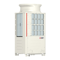
What to do if my Mitsubishi Electric PUHY-P250YJM-A shows a high-pressure sensor fault?
- AAshley JonesSep 9, 2025
The suggested solution for a high-pressure sensor fault in your Mitsubishi Electric Air Conditioner is 5201.
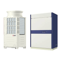
What to do if my Mitsubishi Electric PUHY-P250YJM-A shows a high-pressure sensor fault?
The suggested solution for a high-pressure sensor fault in your Mitsubishi Electric Air Conditioner is 5201.
What to do if my Mitsubishi Electric PUHY-P250YJM-A displays a power supply signal sync error?
If your Mitsubishi Electric Air Conditioner has a power supply signal sync error, the suggested solution is 4115.
What to do if my Mitsubishi Electric Air Conditioner has an abnormal bus voltage drop?
If your Mitsubishi Electric Air Conditioner is displaying an abnormal bus voltage drop, the suggested solutions are 4220 4225 (Note), 4320 4325 (Note).
| Refrigerant | R410A |
|---|---|
| Power Supply | 380-415V, 50Hz |
| Indoor Unit Dimensions (W x H x D) | Varies depending on the connected indoor units |
| Weight (Indoor Unit) | Varies depending on the connected indoor units |
| Operating Temperature (Cooling) | -5 to 46 °C |
Covers warnings, cautions, and general safety instructions for unit operation and installation.
Details on using appropriate piping materials and avoiding contamination for R410A systems.
Guidelines on unit placement, environmental considerations, and preventing hazards.
Essential safety measures for grounding, wiring, and circuit breakers during electrical installation.
Crucial steps to perform before initiating the unit's test run operation.
Lists essential tools and materials required for installation and servicing.
Specifies requirements for copper pipe materials, radial thickness, and flare processing.
Procedures for conducting air tightness tests and vacuum drying (evacuation) of the system.
Guidelines for proper refrigerant charging and steps to address refrigerant leaks.
Details on compatible outdoor and indoor unit combinations and system configurations.
Specifies cable requirements and maximum lengths for transmission and remote controller wiring.
Instructions for configuring unit address settings and switch functions for proper operation.
Defines maximum allowable piping lengths and equivalent lengths for different system configurations.
Identifies key components of the outdoor unit and illustrates the refrigerant circuit diagram.
Details the contents and safety precautions related to the outdoor unit's control box.
Explains the layout and functions of the outdoor unit's control and M-NET boards.
Provides dimensional drawings and specifications for various indoor unit models.
Illustrates the internal components and structure of different indoor unit types.
Step-by-step instructions for replacing the fan pulley and motor assembly.
Outlines the features, specifications, and wiring methods for the MA remote controller.
Instructions on selecting the temperature detection source for accurate room temperature control.
Provides detailed electrical wiring diagrams for the outdoor unit.
Details electrical wiring diagrams for standard and fresh air intake indoor units.
Illustrates the electrical connections for the transmission booster.
Visual representation of the refrigerant flow paths within the outdoor unit.
Explains the function and specifications of key refrigerant circuit components.
Details the functions and factory settings of the outdoor unit's control board dipswitches.
Describes outdoor unit designation (OC/OS), startup sequence rotation, and initial control processes.
Explains how to prohibit cooling/heating operation using external signals for demand control.
Provides flowcharts illustrating indoor and outdoor unit mode determination and operation logic.
Lists essential checks to perform before initiating the test run procedure.
Step-by-step guide on how to perform a test run using the MA remote controller.
Details symptoms of incorrect refrigerant charge and procedures for adjustment.
Instructions for entering and using the refrigerant amount adjustment mode.
Provides reference data for operating conditions, pressures, and temperatures for single and multi-unit systems.
Comprehensive list of error codes, their definitions, and affected units.
Guide on interpreting error codes displayed on the remote controller and troubleshooting steps.
Detailed troubleshooting procedures for key components like sensors, valves, and motors.
Step-by-step instructions for safely removing and replacing the compressor.
Explains how to interpret the 7-segment LED displays and their numerical/flag outputs.
Describes the unit's clock function for calculating operating time and storing error history.
