4 - 44
CPU MODULE4.
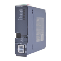
No. Name Description
1) Module fixing hook
Hook for fixing the module to the base unit
(Single-motion installation)
2) MODE LED
Indicates the mode of the CPU.
On (orange): A mode
On (green): Q mode
3) RUN LED
Indicates the operation status of the CPU.
On: During operation in "RUN" or "STEP RUN" mode
Off: During a stop in "STOP", "PAUSE" or "STEP RUN" mode, or an error that
stops operation has occurred.
4) ERR. LED
On: A self-diagnostics error that does not stop operation, other than a battery
error, has been detected.
(When the parameter setting is made for operation to continue when an
error occurs.)
Off: Normal
Flicker: An error that stops operation has been detected.
5) USER LED
On: Annunciator F is turned on.
Off: Normal
Flicker: Latch clear is performed.
6) BAT. LED
On: A battery error has occurred due to low battery voltage of the CPU
module and memory card.
Off: Normal
7) BOOT LED
On: Boot operation in execution
Off: Boot operation not in operation
8) Serial number Shows the serial number printed on the rating plate.
9) Memory card EJECT button Used for ejecting the memory card from the CPU module.
10)
Memory card installing
connector
Connector for installing the memory card in the CPU module
11) USB connector Unusable (Usable for Q mode only)
12) RS-232 connector
Connector for connecting to a peripheral device
Connectable with the RS-232C connection cable (QC30R2)
 Loading...