Do you have a question about the Mitsubishi Electric Q64AD2DA and is the answer not in the manual?
Precautions related to the design and implementation of the intelligent function module.
Guidelines for safely mounting and installing the module to prevent damage or malfunction.
Guidelines for safe and effective wiring to prevent noise and electrical hazards.
Precautions for safe startup, handling, and maintenance of the module.
Describes the capabilities of the Q64AD2DA, including A/D and D/A conversion.
Details the applicable modules, base units, software, and systems for the Q64AD2DA.
How to check the Q64AD2DA and GX Configurator software versions.
Presents the performance specifications, including A/D and D/A conversion characteristics.
Explains the relationship between analog input and digital output for A/D conversion.
Describes the relationship between digital input and analog output for D/A conversion.
Lists the main functions of the Q64AD2DA, such as A/D conversion and scaling.
Explains different A/D conversion methods like sampling, time average, count average, and moving average.
Describes how the module holds and resets the maximum and minimum digital output values.
Explains how to convert digital output values to scaling values (ratio %) and store them.
Explains how to add a setting quantity to a digital output value for adjustment.
Details how the module detects input voltage or current values outside the set ranges.
Increases input ranges for 4-20mA and 1-5V to monitor values below standard ranges.
Explains how to collect and store A/D converted digital output or scaling values.
Sets whether D/A conversion values or offset values are output for each channel.
Allows setting to hold or clear analog output when CPU is stopped or in error.
Describes how to perform an analog output test while the CPU module is in stop status.
Changes the input range of digital input values to a specified range between -32000 and 32000.
Adds a setting quantity to a digital input value to shift the analog output value.
Sets whether A/D or D/A conversion for channels is enabled or disabled.
Lists the input (X) and output (Y) signals for the Q64AD2DA and their functions.
Details the Q64AD2DA's input signals, including module ready and error flags.
Details the Q64AD2DA's output signals, such as logging hold request and output enable/disable flags.
Explains the buffer memory assignments for A/D conversion, D/A conversion, and common areas.
Sets whether A/D conversion for Channel 1 is enabled or disabled.
Sets the time or number of times for averaging processing for Channel 1.
Sets whether to enable or disable A/D conversion scaling for Channel 1.
Sets the scaling range of converted digital output values for Channel 1.
Sets the quantity to be shifted by the shifting function (A/D conversion) for Channel 1.
Sets whether to output a warning or stop for input signal errors detected.
Sets the value for detecting input analog value errors for Channel 1.
Sets whether to enable or disable data logging for Channel 1.
Sets the storing cycle of data for logging and its unit for Channel 1.
Sets the data to be logged during the logging facility use for Channel 1.
Sets the amount of data to be logged after a hold trigger occurrence for Channel 1.
Sets the conditions for using level triggers during logging facility use for Channel 1.
Sets an address of buffer memory monitoring a level trigger for occurrence in Channel 1.
Sets a value that makes level triggers work for Channel 1.
Stores the A/D converted digital output value for Channel 1.
Stores scaled and shifted values for A/D conversion for Channel 1.
Stores the maximum and minimum digital output values converted for Channel 1.
Stores the maximum and minimum scaling values converted for Channel 1.
Checks the analog input range settings for Channel 1.
Checks the A/D conversion status for Channel 1.
Checks the input signal status for Channel 1, indicating normal or error conditions.
Checks the address of buffer memory storing the oldest data in the logging area for Channel 1.
Checks the address of buffer memory storing the latest data in the logging area for Channel 1.
Checks the amount of data stored in the logging data storage area for Channel 1.
Checks the address of area storing data at the point of hold trigger occurrence for Channel 1.
Checks latest error codes and error time detected by the Q64AD2DA.
Sets whether to enable or disable D/A conversion for Channel 5.
Writes digital input values from the CPU module for D/A conversion for Channel 5.
Sets whether to enable or disable D/A conversion scaling for Channel 5.
Sets the scaling range of converted digital input values for Channel 5.
Sets the quantity to be shifted using the shifting function (D/A conversion) for Channel 5.
Checks whether digital values outside settable range are set for Channel 5.
Checks digital values equivalent to output analog values for Channel 5.
Checks the analog output range settings for Channel 5.
Checks the analog output HOLD/CLEAR function settings for Channel 5.
Stores level data used for monitoring to make level triggers work.
Shows the buffer memory address storing the latest error history.
Stores up to 16 error logs that occurred in the Q64AD2DA.
Important precautions for handling the module to prevent damage, failure, or injury.
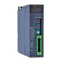
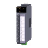
Identifies and describes the main parts and LEDs of the Q64AD2DA module.
Provides essential precautions for wiring to ensure reliable and noise-resistant operation.
Illustrates external wiring examples for analog input and output signals.
Details how to connect the external power supply connector, including cable specifications.
Explains how to perform detailed settings for the intelligent function module in GX Developer.
Details how to configure input range, output range, and resolution mode settings via switches.
Explains how to correct offset/gain using scaling and shift functions.
Lists the functions provided by the utility package for initial setting and monitoring.
Provides safety and installation precautions for using GX Configurator-AD/DA with GX Developer.
Specifies the operating environment requirements for the personal computer running GX Configurator.
Explains common operations, control keys, and data handling within the utility package.
Provides an overview of the operational steps and windows within GX Configurator-AD/DA.
Details how to start and use the Intelligent Function Module utility within GX Developer.
Guides through configuring initial settings for each channel of the Q64AD2DA.
Explains how to set buffer memory for auto-refreshing data.
Details the Monitor/Test window for checking buffer memory and I/O signals.
Describes how to convert initial and auto refresh settings into Function Blocks (FBs).
Explains the procedures for creating and using Function Blocks (FBs) with GX Developer.
Explains the procedures for creating programs involving A/D or D/A conversion with the Q64AD2DA.
Provides program examples for a normal system configuration using the Q64AD2DA.
Details the necessary works before creating programs, including wiring and switch settings.
Provides a program example demonstrating the use of the utility package for initial setup.
Provides a program example without the utility package, focusing on direct programming.
Explains program examples for using the Q64AD2DA in a remote I/O network configuration.
Details wiring and switch settings required before programming for a remote I/O network.
Shows a program example using the utility package for remote I/O network setup.
Provides a program example without the utility package for remote I/O network setup.
Outlines the requirements and conditions necessary for performing an online module change.
Details the step-by-step operations involved in changing a module online.
Describes online module change when initial settings are configured via GX Configurator.
Details the online module change process when initial settings are done via sequence program.
Lists error codes, their descriptions, and corrective actions for the Q64AD2DA.
Troubleshooting steps for when the RUN LED on the module is off.
Troubleshooting steps for when the ERR LED is on or blinking.
Troubleshooting steps for when the ALM LED blinks.
Troubleshooting steps for issues where digital output values cannot be read.
Troubleshooting steps when the A/D conversion completed flag does not activate.
Troubleshooting steps when no analog output value is produced.
Troubleshooting steps when the External power off flag (X6) is turned on.
How to check the Q64AD2DA status, including error codes and LED status using GX Developer.
Provides the physical dimensions of the Q64AD2DA module in millimeters.
| Product Series | Q Series |
|---|---|
| Number of Channels | 4 |
| Input Channels | 4 |
| Output Channels | 2 |
| Operating Temperature | 0 to 55°C |
| Storage Temperature | -25 to 75°C |
| Type | Analog I/O Module |
| Input Signal Range | Voltage: -10 to +10 V, Current: 4 to 20 mA |
| Output Signal Range | Voltage: -10 to +10 V, Current: 4 to 20 mA |
| Resolution | 1/4000 |
| Isolation | Photocoupler isolation between input/output |
| Power Supply | 5V DC (supplied from the base unit) |
| Input Range | Voltage: -10 to +10 V, Current: 4 to 20 mA |
| Output Range | Voltage: -10 to +10 V, Current: 4 to 20 mA |
| Conversion Speed | 1 ms/channel |
| Weight | 0.2 kg |