19
(2) Precautions for connection
(a) Connect the FG signal line and shield of the RS-232 cable as
follows:
(b) When data communication cannot be performed normally due
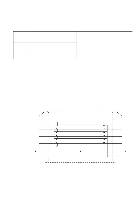
to external noise, connect the wires as follows:
1) Connect the FG terminals of both stations with the shield of
the RS-232 cable.
For the external device side, refer to the handling
instructions for the external device.
2) Each signal line (except for SG) must be twisted with the
SG signal line.
3) FG of the AJ65BT-R2N is connected to the screw clamp of
the connector, acting as FG of the module.
(c) Do not connect an RS-422 device to the RS-232 interface.
Doing so will damage the RS-422 interface of the connected
device, resulting in communication failure.
Table 5.3 Precautions for connection
RS-232 cable Connection method Remarks
FG signal
Connected to the screw clamp of
the AJ65BT-R2N side connector.
• Do not short-circuit the FG and SG signal
lines of the RS-232 cable.
• If the FG and SG signal lines are
connected inside the external-device
side, do not connect the FG signal line on
the AJ65BT-R2N side to the external
device.
Shield
Connected to the screw clamp of
the AJ65BT-R2N side connector.
(Not connected to external
device)
Figure 5.2 Precautions for connection
Connector chassis
(AJ65BT-R2N side)
SD
RD
DSR
DTR
SG
RD
FG
SD
DTR
DS
SG
Shield (External device side)
 Loading...


