18
5.2 External Device Connection Method
(1) Connection examples
The AJ65BT-R2N cannot use the CD signal as the control signal for
sending/receiving data to/from the external device.
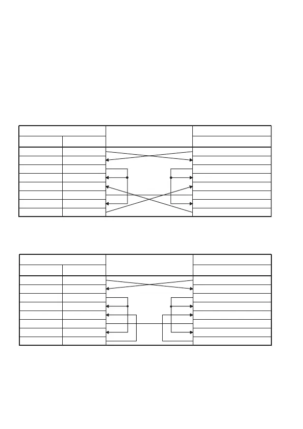
Wire the CD signal line of the AJ65BT-R2N and external device as
shown in Table 5.1.
(a) Connection example where DC code control and DTR/DSR
(ER/DR) control are executable
(b) Connection example only DC code control is executable
Table 5.1 DC code control and DTR/DSR (ER/DR) control
Table 5.2 Connection example only DC code control is executable
AJ65BT-R2N side (DTE)
Signal name Pin No.
Cable connection and signaling
External device (DTE)
Signal name
SD 3
RD 2
RS 7
CS 8
DR 6
SG 5
CD 1
ER
SD
RD
RS
CS
DR
SG
CD
ER4
AJ65BT-R2N side (DTE)
Signal name Pin No.
Cable connection and signaling
External device (DTE)
Signal name
SDSD 3
RD 2
RS 7
CS 8
DR 6
SG 5
CD 1
ER
RD
RS
CS
DR
SG
CD
ER4
 Loading...


