10
3. IMPLEMENTATION AND INSTALLATION
3.1 Handling Precautions
(1) Tighten the module installation screws within the following ranges.
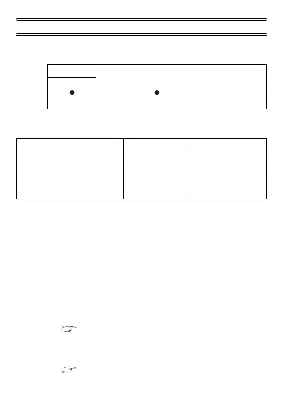
(2) When using the DIN rail adapter, pay attention to the following.
(a) Applicable DIN rail type (Compliant with IEC 60715)
• TH35-7.5Fe
• TH35-7.5Al
•TH35-15Fe
(b) DIN rail installation screw pitch
When installing a DIN rail, tighten the screws at a pitch of
200mm or less.
3.2 Installation Environment
(1) AJ65BT-R2N
For the AJ65BT-R2N installation environment, refer to the
following.
Section 2.1 General Specifications
(2) CC-Link
For the installation environment for the CC-Link system, refer to the
following.
User's Manual for the master module to be used
POINT
For handling precautions on installation or removal of the module,
read SAFETY PRECAUTIONS provided at the beginning of this
manual.
Table 3.1 Screw tightening torque
Screw Tightening toque range Remarks
Module installation screw (M4) 0.78 to 1.18N•m -
Terminal block terminal screw (M3.5) 0.59 to 0.88N•m -
Terminal block installation screw (M4) 0.98 to 1.37N•m -
RS-232 cable connector screw (M2.6) 0.20 to 0.39N•m
Screw hole depth:
L=3.2mm or less
(Internal dimension from
end face)
 Loading...


