11
4. PART NAMES AND SETTINGS
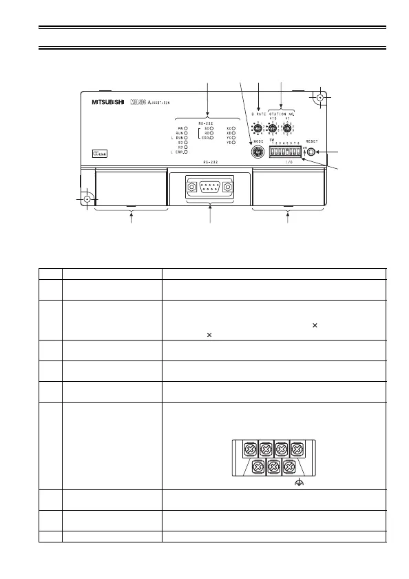
Figure 4.1 AJ65BT-R2N outline view
Table 4.1 Part names
No. Name Description
1) Indicator LEDs
Indicate the operating status of the AJ65BT-R2N.
For details, refer to (1) in this section.
2)
Station No. setting
switches
Set a station No. for the AJ65BT-R2N. (Factory default: 0)
Setting range: 1 to 64
Set the tens place of the station No. with " 10", and the ones
place with " 1".
3)
Data link transmission
speed setting switch
Set the transmission speed of the AJ65BT-R2N.
For details, refer to (2) in this section.
4) Mode setting switch
Set the operation status of the AJ65BT-R2N.
For details, refer to (3) in this section.
5)
RS-232 transmission
setting switches
Set the RS-232 transmission specifications.
For details, refer to (4) in this section.
6) Data link terminal block
Connect a CC-Link dedicated cable for power supply and
data link. (Detachable terminal block)
7) RS-232 interface
Connect an RS-232 cable for connection to an external
device.
8)
General-purpose I/O
terminal block
Connect input/output wires. (Detachable terminal block)
9) Reset switch Used to return to the power-up status.
1) 4) 3) 2)
9)
5)
6) 7) 8)
DA DG +24V
DB SLD
FG
24G
 Loading...


